1. Einleitung
This manual provides detailed instructions for the installation, operation, maintenance, and troubleshooting of the ASUS P7F-M Micro ATX Motherboard. Please read this manual thoroughly before installing or using the motherboard to ensure proper setup and functionality.
The ASUS P7F-M is designed for Intel Xeon 3400 series, Core i7, Core i5, and Core i3 processors with an LGA 1156 socket, supporting DDR3 memory and offering various expansion and connectivity options.
2. Einrichtung und Installation
Vor Beginn der Installation vergewissern Sie sich, dass Ihr System ausgeschaltet und vom Stromnetz getrennt ist. Tragen Sie ein Antistatikarmband, um Schäden an den Komponenten durch elektrostatische Entladung (ESD) zu vermeiden.
2.1 Motherboard-Layout

Bild: Draufsicht view of the ASUS P7F-M motherboard, showing the CPU socket, RAM slots, PCIe slots, and various connectors.

Bild: Abgewinkelt view of the ASUS P7F-M motherboard, highlighting the rear I/O panel, CPU socket, and expansion slots.
2.2 CPU-Installation
- Suchen Sie den LGA 1156 CPU-Sockel auf dem Motherboard.
- Gently push down the load lever and pull it sideways to open the socket retention frame.
- Richten Sie die CPU vorsichtig am Sockel aus und achten Sie darauf, dass das goldene Dreieck auf der CPU mit dem Dreieck am Sockel übereinstimmt. Drücken Sie die CPU nicht mit Gewalt in den Sockel.
- Schließen Sie den Halterahmen und drücken Sie den Ladehebel wieder in seine Position, bis er einrastet.

Bild: Nahaufnahme view of the LGA 1156 CPU socket on the ASUS P7F-M motherboard, ready for processor installation.
2.3 Speicherinstallation
The motherboard supports 4x DDR3-1333/1066 DIMMs, with a maximum capacity of 16GB. It supports both ECC and non-ECC un-buffered memory.
- Öffnen Sie die Klemmen an beiden Enden des DIMM-Steckplatzes.
- Richten Sie das Speichermodul am Steckplatz aus und achten Sie darauf, dass die Kerbe am Modul mit der entsprechenden Markierung im Steckplatz übereinstimmt.
- Drücken Sie beide Enden des Speichermoduls fest nach unten, bis die Klammern einrasten.
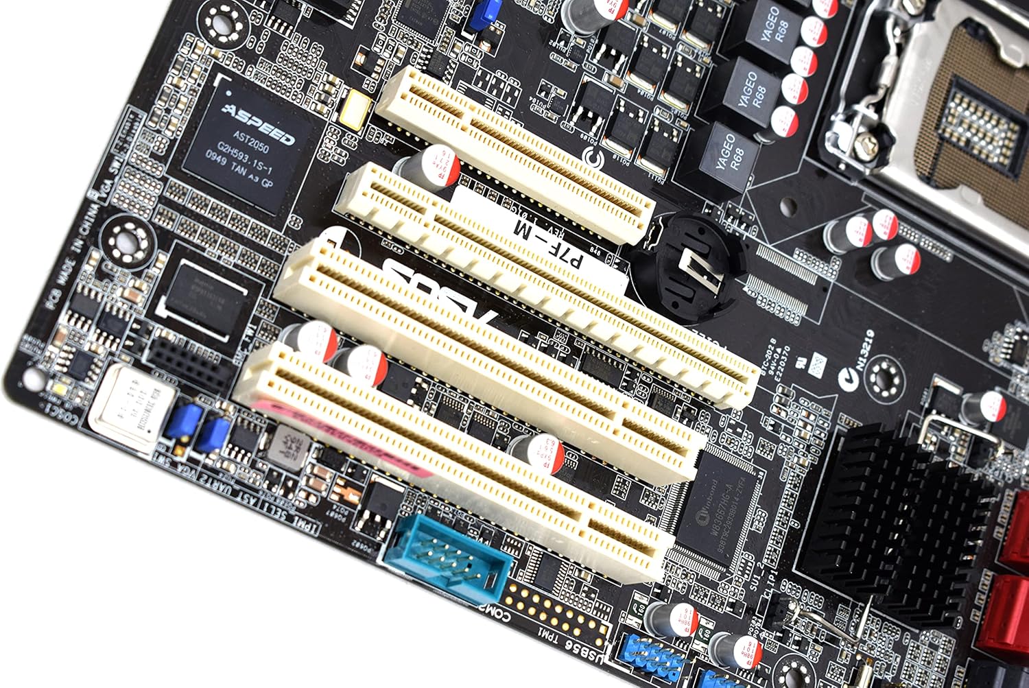
Bild: Nahaufnahme view of the four DDR3 DIMM slots on the ASUS P7F-M motherboard, showing their arrangement.
2.4 Installation der Erweiterungskarte
The motherboard features:
- 1x PCI-Express x16 Slot
- 1x PCI-Express x8 Slot (operates at x4)
- 2x 32bit/33MHz PCI Slots
- Select an appropriate expansion slot for your card.
- Remove the corresponding metal slot cover from your PC case.
- Align the card with the slot and press down firmly until it is securely seated.
- Befestigen Sie die Karte mit einer Schraube am PC-Gehäuse.

Bild: Nahaufnahme view of the PCI Express and PCI expansion slots on the ASUS P7F-M motherboard.
2.5 Anschluss eines Speichermediums
Connect your SATA storage devices (HDDs, SSDs, optical drives) to the SATA ports on the motherboard.

Bild: Nahaufnahme view of the SATA ports on the ASUS P7F-M motherboard, typically located near the chipset.
2.6 Stromanschlüsse
Connect the 24-pin ATX main power connector and the 8-pin CPU power connector from your power supply unit (PSU) to the corresponding ports on the motherboard.
2.7 Anschlüsse auf der Rückseite
Schließen Sie Peripheriegeräte an die hinteren I/O-Anschlüsse an:
- USB 2.0 Ports: Für Tastaturen, Mäuse und andere USB-Geräte.
- PS/2-Anschlüsse: For legacy PS/2 keyboards and mice.
- RJ45-LAN-Anschlüsse: Für die Netzwerkkonnektivität.
- Serielle Schnittstelle: For serial devices.
- VGA-Anschluss: Zur Videoausgabe an einen Monitor.
3. Bedienungsanleitung
3.1 Erstes Einschalten
After all components are installed and connected, connect the power cable to your PSU and press the power button on your PC case. The system should initiate the Power-On Self-Test (POST).
3.2 BIOS/UEFI-Einrichtung
Drücken Sie während des POST-Vorgangs die angegebene Taste (normalerweise DEL or F2) to enter the BIOS setup utility. Here you can configure system settings, boot order, and monitor hardware status.
3.3 Treiberinstallation
After installing your operating system, install the necessary drivers for the motherboard chipset, LAN, and any other integrated components. These drivers are typically provided on a support CD or available for download from the ASUS webWebsite.
4. Wartung
4.1 Reinigung
Reinigen Sie das Innere Ihres Computers regelmäßig, um Staubansammlungen zu vermeiden, die zu Überhitzung und Bauteilausfällen führen können. Verwenden Sie Druckluft, um Staub von Lüftern, Kühlkörpern und anderen Komponenten zu entfernen. Stellen Sie sicher, dass das System ausgeschaltet und vom Stromnetz getrennt ist, bevor Sie mit der Reinigung beginnen.
4.2 BIOS-Updates
Überprüfen Sie regelmäßig den ASUS-Support. website for updated BIOS versions. BIOS updates can improve system stability, add support for new hardware, or fix bugs. Follow the instructions provided by ASUS carefully when performing a BIOS update to avoid system damage.
5. Fehlerbehebung
If you encounter issues with your ASUS P7F-M motherboard, consider the following troubleshooting steps:
- Kein Strom: Ensure all power cables (24-pin ATX, 8-pin CPU) are securely connected. Verify the PSU is functioning correctly.
- Kein Bildschirm: Check that the monitor is connected to the correct video output (VGA on the motherboard or a dedicated graphics card). Reseat the graphics card and memory modules.
- Systeminstabilität: This can be caused by incompatible memory, insufficient power, or overheating. Verify memory compatibility and check CPU/case fan operation.
- POST-Pieptöne: Listen for beep codes during startup. Refer to the ASUS website or a general BIOS beep code guide to diagnose the issue.
- Component Detection Issues: Ensure all components (CPU, RAM, expansion cards, storage drives) are properly seated and connected.
Weitere Unterstützung erhalten Sie beim ASUS-Support. webBesuchen Sie die Website oder kontaktieren Sie deren technischen Support.
6. Spezifikationen
Below are the detailed technical specifications for the ASUS P7F-M Motherboard:
| Besonderheit | Spezifikation |
|---|---|
| CPU-Sockel | LGA 1156 |
| Kompatible Prozessoren | Intel Quad Core Xeon 3400 series, Core i7-800, Core i5-700, Core i3 series |
| Chipsatz | Intel 3420 PCH Chipset |
| Memory Slots | 4x DDR3 DIMMs |
| Speichertyp | DDR3-1333/1066, Dual Channel, Un-buffered, ECC/non-ECC |
| Maximale Speicherkapazität | 16 GB |
| PCI-Express x16-Steckplätze | 1 |
| PCI-Express x8-Steckplätze | 1 (runs in x4 mode) |
| PCI-Steckplätze | 2x 32bit/33MHz |
| LAN-Controller | Intel 82574L Dual Port Gigabit LAN controller, 1x Management LAN |
| USB 2.0-Anschlüsse | 7 (2 rear, 5 via header) |
| PS/2-Anschlüsse | 2 |
| RJ45-LAN-Anschlüsse | 3 |
| Serielle Schnittstellen | 2 (1 rear, 1 via header) |
| VGA-Anschluss | 1 |
| Hauptstromanschluss | 1x 24-polig |
| CPU-Stromanschluss | 1x 8-polig |
| Formfaktor | Micro ATX |
| Maße | 13.3 x 11.1 x 3.1 Zoll (Verpackung) |
| Artikelgewicht | 1.5 Pfund |
7. Garantie und Support
For information regarding the product warranty, please refer to the warranty card included with your motherboard or visit the official ASUS website. ASUS provides technical support and resources, including driver downloads, FAQs, and contact information, on their support portal.
ASUS-Kundendienst WebWebsite: https://www.asus.com/support/