
1. Einleitung
The MASTECH MY70 is a reliable and versatile digital multimeter designed for basic electrical measurements. It is suitable for a wide range of applications, including workshop use, hobby projects, and general electrical testing. This manual provides essential information for the safe and effective operation, maintenance, and troubleshooting of your MY70 multimeter.
2. Sicherheitshinweise
Always observe the following safety precautions to prevent personal injury and damage to the multimeter or equipment under test.
- Read and understand all instructions in this manual before using the multimeter.
- Die maximalen Eingabewerte für keine Funktion dürfen überschritten werden.
- Seien Sie vorsichtig beim Arbeiten mit VolumentagEs liegt über 30 V AC RMS, 42 V Spitze oder 60 V DC. Diese SpannungentagEs besteht die Gefahr eines Stromschlags.
- Vor dem Ändern von Funktionen oder Messbereichen müssen die Messleitungen immer vom Stromkreis getrennt werden.
- Inspect test leads for damaged insulation or exposed metal before each use. Replace if damaged.
- Vor dem Betrieb sicherstellen, dass der Batteriedeckel fest verschlossen ist.
- Das Multimeter darf nicht bedient werden, wenn es beschädigt erscheint oder das Gehäuse geöffnet ist.
- Halten Sie sich an lokale und nationale Sicherheitsvorschriften.
This device complies with IEC 61010, CE, and RoHS standards.
3. Produktmerkmale
The MASTECH MY70 Digital Multimeter offers a range of essential measurement capabilities:
- AC- und DC-Voltage Messung
- AC- und DC-Strommessung
- Widerstandsmessung
- Diodentest
- Durchgangsprüfung mit Summer
- Transistor-hFE-Test
- Datenhaltefunktion
- Automatische Abschaltung
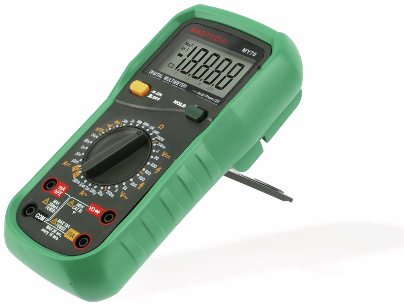
Abbildung 3.1: Vorderseite view of the MASTECH MY70 Digital Multimeter.
4. Packungsinhalt
Überprüfen Sie, ob alle Artikel in Ihrem Paket vorhanden sind:
- MASTECH MY70 Digitalmultimeter
- Messleitungen (eine rote, eine schwarze)
- 9V Battery (NEDA 1604 or 6F22 type)
- Transistor Test Socket (hFE adapter)
- Benutzerhandbuch (dieses Dokument)
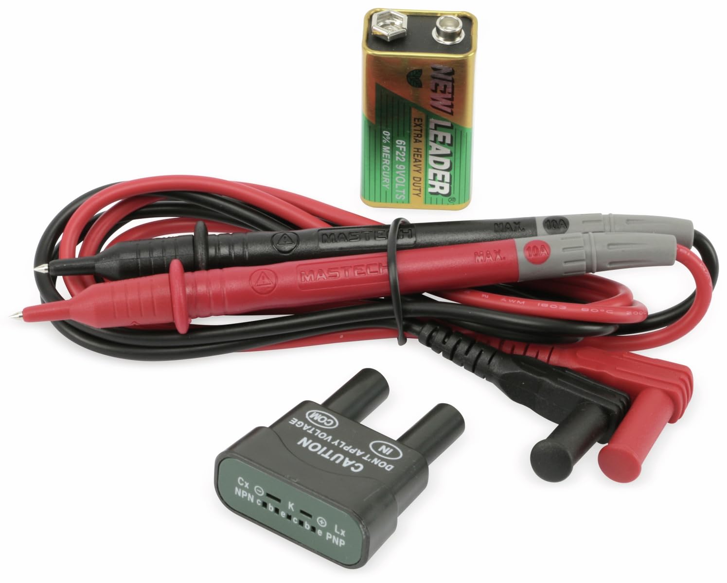
Figure 4.1: MASTECH MY70 Multimeter accessories.
5. Einrichtung
5.1 Einlegen der Batterie
- Stellen Sie sicher, dass das Multimeter ausgeschaltet ist.
- Suchen Sie das Batteriefach auf der Rückseite des Geräts.
- Lösen Sie die Befestigungsschraube(n) und entfernen Sie die Batterieabdeckung.
- Schließen Sie die 9V-Batterie unter Beachtung der richtigen Polarität an die Batterieklemmen an.
- Setzen Sie die Batterie in das Batteriefach ein und bringen Sie den Deckel wieder an. Befestigen Sie ihn anschließend mit der/den Schraube(n).

Abbildung 5.1: Rückseite view mit Batteriefach.
5.2 Anschließen der Testleitungen
For most measurements, connect the black test lead to the "COM" (common) jack and the red test lead to the "VΩmA" jack. For high current measurements (up to 10A), connect the red lead to the "10A" jack.
6. Bedienungsanleitung
To begin, turn the rotary switch to the desired function and range. Connect the test leads to the circuit or component under test.
6.1 DC-Voltage Messung (V=)
- Set the rotary switch to the desired "V=" range (e.g., 20V, 200V).
- Verbinden Sie die schwarze Messleitung mit der "COM"-Buchse und die rote Messleitung mit der "VΩmA"-Buchse.
- Schließen Sie die Messleitungen parallel an die Gleichspannung an.tage Quelle oder Komponente.
- Lesen Sie den Bandtage-Wert auf dem Display.
6.2 AC-Voltage Messung (V~)
- Set the rotary switch to the desired "V~" range (e.g., 200V, 600V).
- Verbinden Sie die schwarze Messleitung mit der "COM"-Buchse und die rote Messleitung mit der "VΩmA"-Buchse.
- Schließen Sie die Messleitungen parallel an die Wechselstromspannung an.tage Quelle oder Komponente.
- Lesen Sie den Bandtage-Wert auf dem Display.
6.3 Gleichstrommessung (A=)
Vorsicht: Schließen Sie das Multimeter bei Strommessungen immer in Reihe mit dem Stromkreis an. Schließen Sie es niemals parallel zu einer Spannung an.tagDie Quelle.
- Set the rotary switch to the desired "A=" range (e.g., 200µA, 10A).
- For currents up to 200mA, connect the red test lead to the "VΩmA" jack. For currents up to 10A, connect the red test lead to the "10A" jack. The black lead always connects to "COM".
- Öffnen Sie den Stromkreis, in dem der Strom gemessen werden soll, und schließen Sie das Multimeter in Reihe an.
- Lesen Sie den aktuellen Wert auf dem Display ab.
6.4 Widerstandsmessung (Ω)
Vorsicht: Vor der Widerstandsmessung muss sichergestellt werden, dass der Stromkreis stromlos ist und alle Kondensatoren entladen sind.
- Set the rotary switch to the desired "Ω" range (e.g., 200Ω, 2MΩ).
- Verbinden Sie die schwarze Messleitung mit „COM“ und die rote Messleitung mit „VΩmA“.
- Connect the test leads across the component whose resistance is to be measured.
- Lesen Sie den Widerstandswert auf dem Display ab.
6.5 Diodentest (→|)
- Set the rotary switch to the "→|" Position.
- Verbinden Sie die schwarze Messleitung mit „COM“ und die rote Messleitung mit „VΩmA“.
- Schließen Sie die rote Leitung an die Anode und die schwarze Leitung an die Kathode der Diode an. Eine Durchlassspannungtage drop (typically 0.5V to 0.8V for silicon diodes) will be displayed.
- Reverse the leads. The display should show "OL" (Overload) for a good diode.
6.6 Kontinuitätsprüfung (•))))
- Set the rotary switch to the "•)))" Position.
- Verbinden Sie die schwarze Messleitung mit „COM“ und die rote Messleitung mit „VΩmA“.
- Schließen Sie die Messleitungen an den Stromkreis oder das Bauteil an.
- Wenn der Widerstand unter etwa 50 Ω liegt, ertönt der Summer, was auf Durchgang hinweist.
6.7 Transistor-hFE-Test
- Stellen Sie den Drehschalter auf die Position "hFE".
- Insert the transistor (NPN or PNP) into the appropriate sockets on the transistor test adapter.
- Lesen Sie den hFE-Wert (Gleichstromverstärkung) auf dem Display ab.
6.8 Datenhaltefunktion
Drücken Sie die Taste „HOLD“, um den aktuellen Messwert auf dem Display einzufrieren. Drücken Sie sie erneut, um die Haltefunktion aufzuheben und die Live-Messungen fortzusetzen.
7. Wartung
7.1 Reinigung
Löschen Sie den Fall mit Anzeigeamp cloth and a mild detergent. Do not use abrasives or solvents. Ensure the multimeter is completely dry before use.
7.2 Batteriewechsel
When the battery symbol appears on the display, the 9V battery needs to be replaced. Refer to Section 5.1 for battery installation instructions.
7.3 Sicherungswechsel
If the current measurement function fails, the fuse may need replacement. The MY70 uses two fuses: a 400mA/250V (F400mA/250V) fuse for the mA range and a 10A/250V (F10A/250V) fuse for the 10A range. To replace a fuse:
- Stellen Sie sicher, dass das Multimeter ausgeschaltet und die Messleitungen abgeklemmt sind.
- Entfernen Sie die Batterieabdeckung und die Batterie.
- Unscrew the additional screws holding the back case.
- Carefully separate the two halves of the case.
- Locate the blown fuse(s) and replace with fuses of the identical type and rating.
- Reassemble the case, ensuring all screws are tightened.
8. Fehlerbehebung
| Problem | Mögliche Ursache | Lösung |
|---|---|---|
| Keine oder nur schwache Anzeige | Schwache oder leere Batterie | Ersetzen Sie die 9-V-Batterie. |
| "OL" (Überlastung) angezeigt | Input value exceeds selected range or open circuit | Select a higher range or check for an open circuit. |
| Falsche Stromanzeige oder keine Stromanzeige | Blown fuse or incorrect lead connection | Check and replace fuse if necessary. Ensure leads are connected in series and to the correct jacks. |
| Inaccurate resistance reading | Component still energized or parallel components affecting reading | Ensure circuit is de-energized. Isolate the component for accurate measurement. |
9. Spezifikationen
| Parameter | Wert |
|---|---|
| Modell | MY70 |
| Hersteller | Mastech |
| Stromquelle | 9V Battery (NEDA 1604 or 6F22) |
| Abmessungen (L x B x H) | 20.5 x 12.5 x 6 cm (ca. 8.07 x 4.92 x 2.36 Zoll) |
| Gewicht | Ca. 567 Gramm (1.25 Pfund) |
| Sicherheitsstandards | IEC 61010, CE, RoHS |
| Maximale Betriebstemperatur | 60 °C (140 °F) |
| DC-Voltage Reichweite | 200 mV, 2 V, 20 V, 200 V, 600 V |
| AC-Lautstärketage Reichweite | 200V, 600V |
| Gleichstrombereich | 200µA, 2mA, 20mA, 200mA, 10A |
| Widerstandsbereich | 200Ω, 2kΩ, 20kΩ, 200kΩ, 2MΩ, 20MΩ |
10. Garantie und Support
For warranty information and technical support, please refer to the official Mastech webBesuchen Sie unsere Website oder wenden Sie sich an Ihren Händler vor Ort. Bewahren Sie Ihren Kaufbeleg als Kaufnachweis für Garantieansprüche auf.
Manufacturer: Mastech
Modellnummer: MY70