1. Einleitung
This manual provides detailed instructions for the installation, operation, and maintenance of your GIGABYTE Z370XP SLI motherboard. Designed for 8th Generation Intel Core processors, this ATX motherboard offers robust performance and features for various computing needs. Please read this manual thoroughly before beginning installation.
2. Hauptmerkmale
- Supports 8th Generation Intel Core Processors.
- Dual Channel DDR4 memory support with 4 DIMM slots.
- USB 3.1 Gen 2 with USB Type-C for high-speed connectivity.
- 2-Way Graphics Support (SLI/CrossFire) for enhanced visual performance.
- Intel Gigabit LAN for stable and fast network connections.
- GIGABYTE UEFI Dual BIOS for system protection and easy configuration.
- APP Center including Easy Tune and Cloud Station Utilities for system management.
- Realtek ALC1220 Codec for high-definition audio.
- ATX Form Factor (305mm x 225mm).
3. Packungsinhalt
Prüfen Sie, ob alle Artikel im Paket enthalten sind. Sollte ein Artikel fehlen oder beschädigt sein, wenden Sie sich bitte an Ihren Händler.
- GIGABYTE Z370XP SLI Motherboard
- (Additional accessories such as SATA cables, I/O shield, and manual may be included depending on the region and retailer.)
4. Einrichtung und Installation
Before installing the motherboard, ensure your system components are compatible and that you have a static-free environment.
4.1 Motherboard Overview

Bild 1: Von oben nach unten view of the GIGABYTE Z370XP SLI Motherboard. This image displays the CPU socket, DIMM slots, PCIe slots, and various headers.

Bild 2: Abgewinkelt view of the GIGABYTE Z370XP SLI Motherboard, highlighting the heatsinks and overall layout.
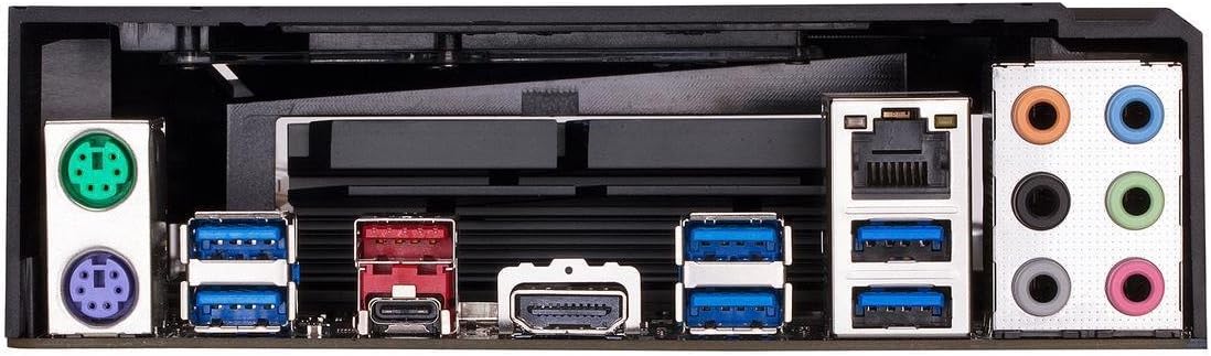
Bild 3: Rear I/O panel of the GIGABYTE Z370XP SLI Motherboard, showing the various ports including USB, HDMI, Ethernet, and audio jacks.
4.2 CPU-Installation
- Suchen Sie den LGA 1151 CPU-Sockel auf dem Motherboard.
- Öffnen Sie den Hebel des CPU-Sockels und entfernen Sie die Schutzkappe.
- Richten Sie die CPU sorgfältig am Sockel aus und achten Sie darauf, dass das goldene Dreieck auf der CPU mit dem Dreieck auf dem Sockel übereinstimmt.
- Setzen Sie die CPU vorsichtig in den Sockel ein, ohne sie mit Gewalt einzusetzen.
- Schließen Sie den Sockelhebel, um die CPU zu sichern.
- Installieren Sie den CPU-Kühler gemäß den Anweisungen des Herstellers.
4.3 Installation des Arbeitsspeichers (RAM)
- Öffnen Sie die Klemmen an beiden Enden der DIMM-Steckplätze.
- Richten Sie die Kerbe am DDR4-Speichermodul an der Kerbe im DIMM-Steckplatz aus.
- Schieben Sie das Speichermodul fest in den Steckplatz, bis die Halteklammern einrasten.
- For dual-channel operation, refer to the motherboard manual for recommended slot configurations.
4.4 Installation des Speichergeräts
- SATA-Laufwerke: Connect SATA data cables from your storage devices (HDDs/SSDs) to the SATA 3 ports on the motherboard. Connect SATA power cables from your power supply to the drives.
- M.2-Laufwerke: Locate the M.2 slots. Insert the M.2 drive at an angle and secure it with the provided screw.
4.5 Installation der Grafikkarte und der Erweiterungskarte
- Open the latch on the desired PCI Express x16 slot.
- Align your graphics card or expansion card with the slot and press down firmly until it is seated.
- Befestigen Sie die Karte mit einer Schraube an Ihrem PC-Gehäuse.
- Schließen Sie alle erforderlichen PCIe-Stromkabel von Ihrem Netzteil an die Grafikkarte an.
4.6 Stromanschlüsse
- Verbinden Sie den 24-poligen ATX-Hauptstromanschluss Ihres Netzteils mit dem entsprechenden Anschluss auf dem Motherboard.
- Connect the 8-pin (or 4+4-pin) ATX 12V CPU power connector to the motherboard.
4.7 Anschlüsse an der Vorderseite
Connect the front panel cables (power button, reset button, HDD LED, power LED, USB ports, audio jacks) to their respective headers on the motherboard. Refer to the motherboard's silkscreen labels for correct orientation.
5. Bedienungsanleitung
5.1 Initial System Boot
- Nachdem alle Komponenten installiert und angeschlossen sind, schließen Sie das PC-Gehäuse.
- Schließen Sie Monitor, Tastatur und Maus an.
- Connect the power cord to your power supply and turn on the power switch.
- Drücken Sie den Netzschalter an Ihrem PC-Gehäuse.
- Das System sollte sich einschalten und den GIGABYTE-Startbildschirm anzeigen.
5.2 BIOS/UEFI-Einrichtung
Um das BIOS/UEFI-Setup-Dienstprogramm aufzurufen, drücken Sie die Taste DEL key repeatedly during the initial boot process. The BIOS allows you to configure system settings such as boot order, CPU/memory frequencies, and peripheral settings. Save changes before exiting.
5.3 Treiberinstallation
After installing your operating system, install the necessary drivers for the motherboard chipset, LAN, audio, and other integrated components. These drivers are typically provided on a support DVD or can be downloaded from the GIGABYTE official webWebsite.
6. Wartung
- Staubentfernung: Regularly clean dust from inside your PC case, especially from fans and heatsinks, to prevent overheating. Use compressed air for best results.
- BIOS-Updates: Überprüfen Sie regelmäßig den GIGABYTE website for BIOS updates. BIOS updates can improve system stability, compatibility, and performance. Follow the instructions provided by GIGABYTE carefully when updating the BIOS.
- Treiber-Updates: Halten Sie Ihre Systemtreiber auf dem neuesten Stand, um optimale Leistung und Kompatibilität mit neuer Software und Hardware zu gewährleisten.
7. Fehlerbehebung
Sollten Probleme auftreten, beachten Sie bitte die folgenden gängigen Schritte zur Fehlerbehebung:
- Kein Strom/Booten nicht möglich:
- Ensure all power cables (24-pin ATX, 8-pin CPU, GPU) are securely connected.
- Check if the power supply is switched on.
- Überprüfen Sie die Verbindung des Netzschalters an der Vorderseite.
- Kein Bildschirm:
- Ensure the monitor is connected to the graphics card (or motherboard if using integrated graphics) and powered on.
- Setzen Sie die Grafikkarte und die Speichermodule neu ein.
- Testen Sie mit einem einzelnen RAM-Riegel in verschiedenen Steckplätzen.
- Systeminstabilität/Abstürze:
- Überprüfen Sie die Temperaturen von CPU und GPU.
- Stellen Sie sicher, dass alle Treiber korrekt installiert und auf dem neuesten Stand sind.
- Führen Sie Speicherdiagnosetools aus, um nach RAM-Fehlern zu suchen.
- BIOS-Einstellungen auf Standardwerte zurücksetzen.
- On-board Readout/Debug LED: The motherboard may feature an on-board debug LED or POST code display. Consult the full GIGABYTE manual for specific code meanings to diagnose boot issues.
8. Spezifikationen
| Besonderheit | Detail |
|---|---|
| Marke | GIGABYTE |
| Modellname | Z370XP SLI |
| CPU-Sockel | LGA 1151 |
| Kompatible Prozessoren | Intel Core der 8. Generation |
| Chipsatztyp | Intel Z370 |
| RAM-Speichertechnologie | DDR4 |
| Speichertaktfrequenz | 2666 MHz (Unterstützt höhere Taktraten über OC) |
| Verfügbare Speichersteckplätze | 4 |
| Ram Memory Maximum Size | 64 GB |
| Grafikkartenschnittstelle | PCI Express |
| Total PCIe Ports | 4 |
| Total SATA Ports | 6 |
| M.2-Steckplätze | 2 |
| Anzahl USB-Anschlüsse | 8 (Rear I/O) + Internal Headers |
| USB 3.1 Gen 2 Typ-C | 1 (Rückseitige Ein-/Ausgänge) |
| Anzahl der Ethernet-Ports | 1 (Intel Gigabit LAN) |
| Total Number of HDMI Ports | 1 |
| S/PDIF-Anschlusstyp | Optisch |
| Hauptstromanschlusstyp | 24-Pin ATX |
| Formfaktor | ATX (305mm X 225mm) |
| Artikelgewicht | 16 Unzen |
| UPC | 889523011324 |
9. Garantieinformationen
The GIGABYTE Z370XP SLI motherboard typically comes with a 3 Jahr eingeschränkte Garantie. Warranty terms and conditions may vary by region and retailer. Please retain your proof of purchase for warranty claims. For detailed warranty information, visit the official GIGABYTE webWebsite.
10. Technischer Support
For further assistance, driver downloads, BIOS updates, or troubleshooting not covered in this manual, please visit the official GIGABYTE support webWebsite: www.gigabyte.com/support. You may also contact GIGABYTE customer service directly.