
1. Einleitung
This manual provides detailed instructions for the safe and effective use of the Bside FWT81 Cable Tracker. This multi-functional handheld tool is designed for telecommunication engineering, wiring engineering, and network maintenance, offering enhanced anti-interference capabilities. It is an essential tool for identifying, testing, and troubleshooting various cable types including network (RJ45) and telephone (RJ11) lines, as well as other metal wires via an adapter.
2. Produktüberschreitungview
The Bside FWT81 Cable Tracker system comprises two main units: a Transmitter and a Receiver. Familiarize yourself with the components of each unit for optimal operation.
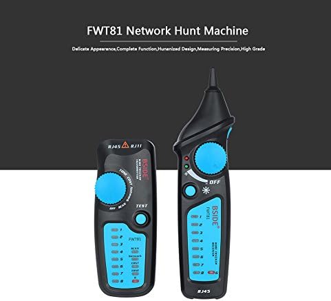
Figure 2.1: The Bside FWT81 Cable Tracker consists of two main units: the Transmitter (left) and the Receiver (right). Both units are designed for ergonomic handling and feature clear indicators and controls.
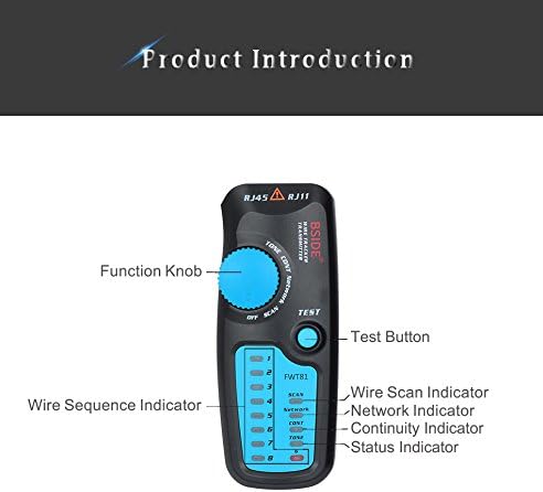
Figure 2.2: This image highlights the key components of the Transmitter unit, including the Function Knob, Test Button, Wire Scan Indicator, Network Indicator, Continuity Indicator, and Status Indicator. It also shows the Wire Sequence Indicator LEDs.
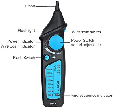
Figure 2.3: This image details the Receiver unit, pointing out the Probe, Flashlight, Power Indicator, Wire Scan Indicator, Flash Switch, Wire Scan Switch, Power Switch with adjustable sound, and the Wire Sequence Indicator LEDs.
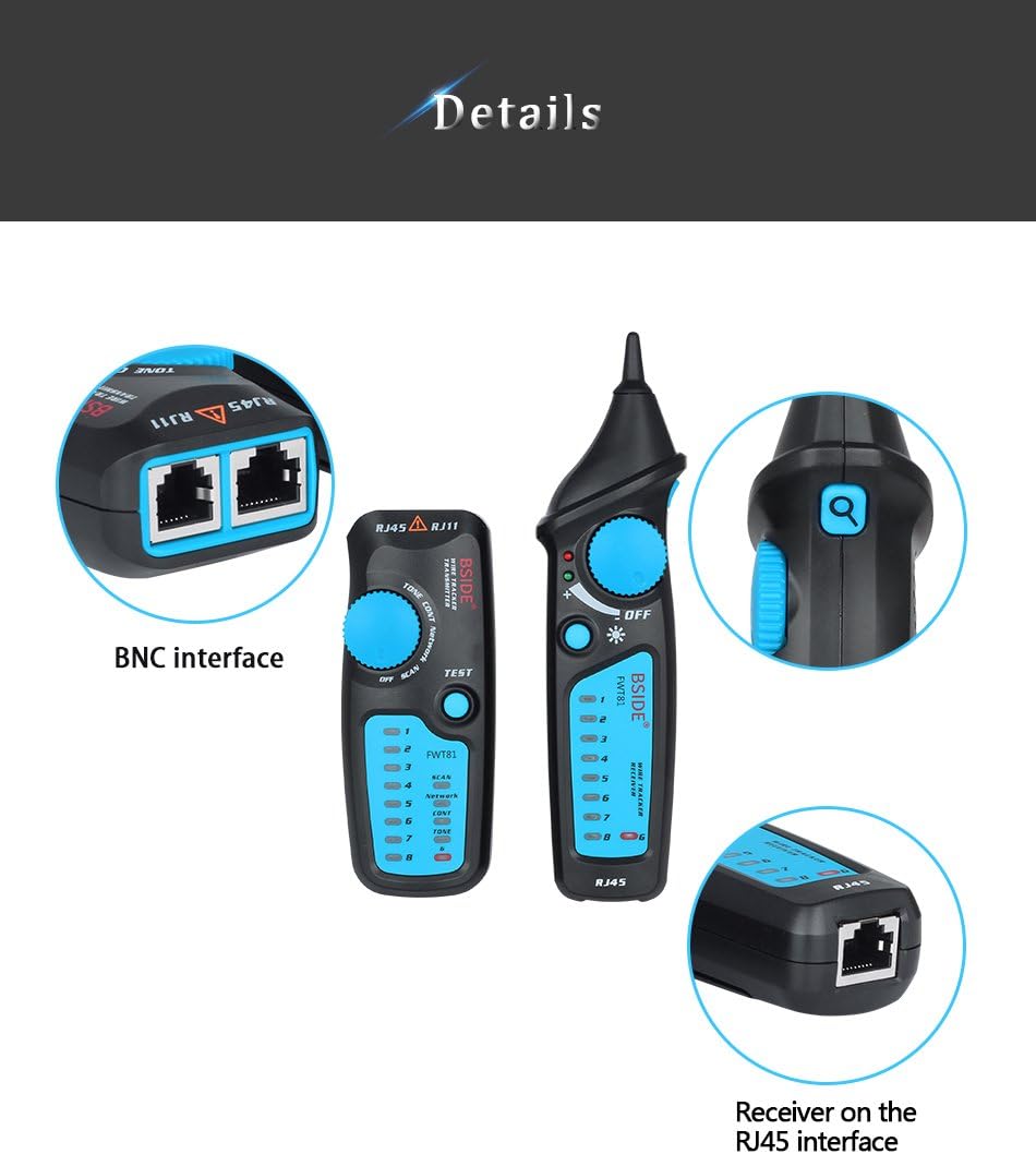
Figure 2.4: A closer look at the interfaces available on the Bside FWT81. The top-left shows the BNC interface, while the bottom-right illustrates the RJ45 interface on the receiver unit. The main units are also shown for context.
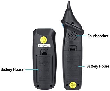
Abbildung 2.5: Dies view shows the rear of both the Transmitter and Receiver units, indicating the location of their respective battery compartments, labeled as 'Battery House'.
3. Einrichtung
3.1 Einlegen der Batterie
Both the Transmitter and Receiver units require a 6F22/9V battery each (not included). To install:
- Locate the battery compartment on the back of each unit (refer to Figure 2.5).
- Öffnen Sie die Batterieabdeckung durch Aufschieben oder Abschrauben.
- Insert a new 6F22/9V battery, ensuring correct polarity (+/-).
- Schließen Sie die Batterieabdeckung fest.
3.2 Anschlusskabel
Connect the cable to be tested to the appropriate port on the Transmitter unit:
- For network cables, use the RJ45 port.
- For telephone lines, use the RJ11 port.
- For other metal wires, use an appropriate adapter connected to the BNC interface (if applicable) or directly to the test clips.
4. Bedienungsanleitung
4.1 Kabelverfolgung
This function allows you to quickly locate specific wire pairs among multiple cables.
- Connect the cable to be traced to the Transmitter's RJ45 or RJ11 port.
- Turn the Function Knob on the Transmitter to the 'SCAN' position.
- Schalten Sie das Empfangsgerät ein.
- Use the Receiver's probe to scan the cables. The Receiver will emit an audible tone, which will be strongest when near the target cable.
- Adjust the sound volume on the Receiver as needed.
4.2 Netzwerkkabelanschluss (RJ45)
This function tests the physical connection status of network cables.
- Connect one end of the network cable to the Transmitter's RJ45 port and the other end to the Receiver's RJ45 port.
- Turn the Function Knob on the Transmitter to the 'TEST' position.
- Observe the Wire Sequence Indicator LEDs on both the Transmitter and Receiver.
- The LEDs will light up in sequence, indicating the status of each wire.
- Interpretieren Sie die Ergebnisse:
- Offener Kreislauf: An LED on one unit lights up, but the corresponding LED on the other unit does not.
- Short Connection: Multiple LEDs light up simultaneously or in an incorrect sequence.
- Miswire/Reverse Connection: LEDs light up, but in an incorrect order between the two units.
4.3 Line Level, Positive and Negative Polarity Test
Use the Transmitter unit only to test the line level and polarity of a circuit.
- Connect the test leads from the Transmitter to the circuit points you wish to test.
- Turn the Function Knob to the appropriate setting for line level/polarity test (refer to the Transmitter's markings).
- Observe the indicators on the Transmitter to determine the line level and polarity.
4.4 Status des Telefonleitungstests
Use the Transmitter unit only to test the operational status of telephone lines.
- Connect the Transmitter to the telephone line via the RJ11 port.
- Turn the Function Knob to the 'TELEPHONE' or equivalent setting.
- The Transmitter will indicate the line status (e.g., ringing, busy, idle).
4.5 Continuity Checking
This instrument can check the continuity of a circuit.
- Connect the test leads from the Transmitter to the two points of the circuit you want to check for continuity.
- Turn the Function Knob to the 'CONT' or 'CONTINUITY' setting.
- A positive indication (e.g., an LED lighting up or an audible tone) signifies continuity.
4.6 Low Battery Capacity Indication
When the battery capacity is low, a dedicated indicator light on the unit will illuminate, signaling that the batteries need to be replaced soon to ensure accurate operation.
5. Wartung
5.1 Reinigung
Reinigen Sie das Gerät mit einem weichen, trockenen Tuch. Verwenden Sie keine Scheuermittel oder Lösungsmittel, da diese das Gerät beschädigen können.asing oder interne Komponenten.
5.2 Speicherung
Store the Bside FWT81 Cable Tracker in a cool, dry place, away from direct sunlight and extreme temperatures. If storing for extended periods, remove the batteries to prevent leakage.
5.3 Batteriewechsel
Replace batteries promptly when the low battery indicator illuminates to ensure consistent performance and accurate readings. Refer to Section 3.1 for battery installation instructions.
6. Fehlerbehebung
- Gerät lässt sich nicht einschalten: Prüfen Sie, ob die Batterien richtig eingesetzt sind und ausreichend geladen sind. Tauschen Sie die Batterien gegebenenfalls aus.
- Kein Signal bei der Kabelverfolgung: Ensure the Transmitter is set to 'SCAN' mode and the Receiver is turned on. Verify the cable connection to the Transmitter. Check battery levels.
- Incorrect network cable collation results: Ensure both ends of the network cable are securely connected to the Transmitter and Receiver. Verify the cable is not damaged.
- Störungen während des Betriebs: The FWT81 has anti-interference enhancement. However, strong electromagnetic fields nearby can still affect results. Try to operate in a less noisy environment.
7. Spezifikationen
| Parameter | Wert |
|---|---|
| Betriebstemperatur und relative Luftfeuchtigkeit | 0-40°C, maximum 80% (non-condensing) |
| Storage Temperature & Relative Humidity | -10-50°C, maximum 80% (non-condensing) |
| Höhe | Weniger als 2000m |
| Anti-explosion Rating | IP40 |
| Distance of Emitting Signal | >300 m |
| Sicherheitsklasse | IEC61010-1 600V CAT III, pollution class II |
| Produktgewicht | 0.180 kg |
| Paketgewicht | 0.270 kg |
| Empfängerabmessungen | 17.5 x 4.5 x 3.5 cm |
| Senderabmessungen | 12 x 4.8 x 3.4 cm |
| Emitter Battery | 6F22/9V (not included) |
| Empfängerakku | 6F22/9V (not included) |
| Stromquelle | Batteriebetrieben, elektrisch |
| UPC | 677892911556 |
8. Garantieinformationen
This product is typically covered by a standard manufacturer's warranty against defects in materials and workmanship. Please refer to the specific warranty card included with your purchase or contact the retailer for detailed warranty terms and conditions. Keep your proof of purchase for any warranty claims.
9. Unterstützung
For technical assistance, troubleshooting beyond this manual, or inquiries regarding your Bside FWT81 Cable Tracker, please contact the retailer or manufacturer's customer support. Contact information can usually be found on the product packaging or the seller's webWebsite.