1. Einleitung
The EPEVER 20A MPPT Solar Charge Controller, model Tracer2210AN, is an advanced Maximum Power Point Tracking (MPPT) device designed for 12V/24V automatic work solar systems. It efficiently manages power flow from solar panels to batteries, ensuring optimal charging and extending battery life. This controller features high conversion efficiency, supports various battery types, and offers comprehensive protection functions. This manual provides essential information for the safe installation, operation, and maintenance of your solar charge controller.

Image 1.1: EPEVER 20A MPPT Solar Charge Controller (Tracer2210AN). This image shows the front view of the solar charge controller with its LCD display and control buttons.
2. Sicherheitshinweise
- Schließen Sie die Batterie immer an den Laderegler an. Erste, then the solar panel, and finally the load. Disconnect in the reverse order: load, then solar panel, then battery.
- Sorgen Sie für ausreichende Belüftung rund um den Controller, um eine Überhitzung zu vermeiden.
- Use appropriate wire gauges for all connections to prevent voltage drop and overheating. Refer to the specifications section for recommended cable sizes.
- Avoid short circuits at all terminals.
- Install the controller in a dry, well-ventilated area, away from direct sunlight and moisture.
- Versuchen Sie nicht, den Controller selbst zu reparieren oder zu modifizieren. Wenden Sie sich für Reparaturen an qualifiziertes Fachpersonal.
- Tragen Sie während der Installation geeignete persönliche Schutzausrüstung (PSA), einschließlich Augenschutz und isolierenden Handschuhen.
3. Produktüberschreitungview
The Tracer2210AN controller incorporates advanced features for efficient solar power management:
- Fortschrittliche MPPT-Technologie: Ensures maximum power extraction from solar panels with tracking efficiency not less than 99.5% and a maximum conversion efficiency of 98%.
- Hochwertige Komponenten: Utilizes international famous brands of ST and IR components for reliability and durability.
- Batteriekompatibilität: Supports various battery types including lead-acid (sealed, gel, flooded) and lithium-ion (LiFePO4, Li(NiCoMn)O2), with user-defined settings.
- Temperaturkompensation: Includes battery temperature compensation function for lead-acid batteries.
- Echtzeitüberwachung: Provides real-time energy statistics and supports communication via RS-485 bus with Modbus protocol for monitoring and parameter setting via mobile APP or PC software (requires optional accessories like MT50, WiFi, or BLE adapters).
- Schutzfunktionen: Features multiple safety protections including overheating power reduction.
3.1 Controller-Komponenten

Bild 3.1: Vorderseite view of the EPEVER Tracer2210AN controller with labeled components. Key components include the LCD display, SELECT and ENTER buttons, remote temperature sensor port, solar panel terminals, battery terminals, load terminals, and an RJ45 communication port.

Abbildung 3.2: Oben und unten views of the EPEVER Tracer2210AN controller. The top view shows the model information and certifications, while the bottom view displays the terminal connections and communication port.
4. Einrichtung
4.1 Montage des Controllers
Mount the controller vertically on a wall or a stable surface. Ensure there is sufficient space around the controller for proper air circulation to dissipate heat. The dimensions of the controller are 220mm x 154mm x 52mm.

Image 4.1: EPEVER MPPT 20A Solar Charge Controller with its physical dimensions indicated. The controller measures 220mm in length, 154mm in width, and 52mm in height.
4.2 Kabelverbindungen
Follow the connection order carefully to avoid damage to the controller or other components. Always connect the battery first, then the solar panel, and finally the load. Disconnect in the reverse order.
- Schließen Sie die Batterie an: Connect the positive and negative terminals of the battery to the corresponding battery terminals on the controller. Ensure correct polarity.
- Schließen Sie das Solarpanel an: Connect the positive and negative terminals of the solar panel to the corresponding PV terminals on the controller. Ensure correct polarity.
- Schließen Sie die Last an: Connect the positive and negative terminals of the DC load to the corresponding load terminals on the controller. Ensure correct polarity.
- Anschluss eines externen Temperatursensors (optional): If using, connect the RTS300R47K3.81A temperature sensor to the designated port on the controller and attach the sensor to the battery for accurate temperature compensation.

Image 4.2: Connection diagram illustrating the proper wiring sequence for the EPEVER solar charge controller. It shows connections from the solar panel, battery (with fuse), and DC load, as well as an optional inverter for AC loads.
5. Bedienungsanleitung
5.1 LCD-Display und Tasten
The controller features an LCD display that shows system status, charging parameters, and error codes. The 'SELECT' and 'ENTER' buttons are used to navigate through menus and adjust settings.
5.2 Einstellungen für den Batterietyp
The controller supports various battery types. It is crucial to select the correct battery type for optimal charging and battery longevity. The default setting is 'Sealed' for lead-acid batteries.
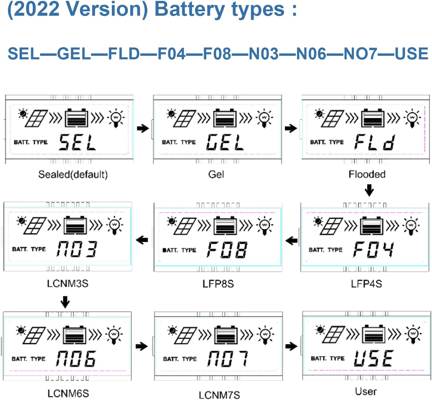
Image 5.1: LCD display showing various battery type selections. Options include Sealed (SEL), Gel (GEL), Flooded (FLD), LiFePO4 (LFP4S, LFP8S), Li(NiCoMn)O2 (LCNM3S, LCNM6S, LCNM7S), and User-defined (USE).
So ändern Sie den Batterietyp:
- Press the 'SELECT' button to cycle through the main display screens until you reach the battery type setting.
- Press and hold the 'ENTER' button to enter the setting modification mode.
- Use the 'SELECT' button to choose the desired battery type (e.g., GEL, FLD, LFP4S, USE).
- Press 'ENTER' again to confirm and save the selection.
5.3 Überwachung und Kommunikation
The Tracer2210AN controller can be monitored and configured remotely using optional accessories:
- MT50 Remote Meter: Connects via RJ45 cable to display real-time data and modify parameters.
- WiFi/BLE Adapters (eBox-WIFI-01, eBox-BLE-01): Connects to the RS-485 port to enable wireless monitoring and control via a mobile application.
- PC Communication Cable (CC-RS485-USB-150U): Connects to a PC for monitoring and parameter setting using EPEVER PC software.
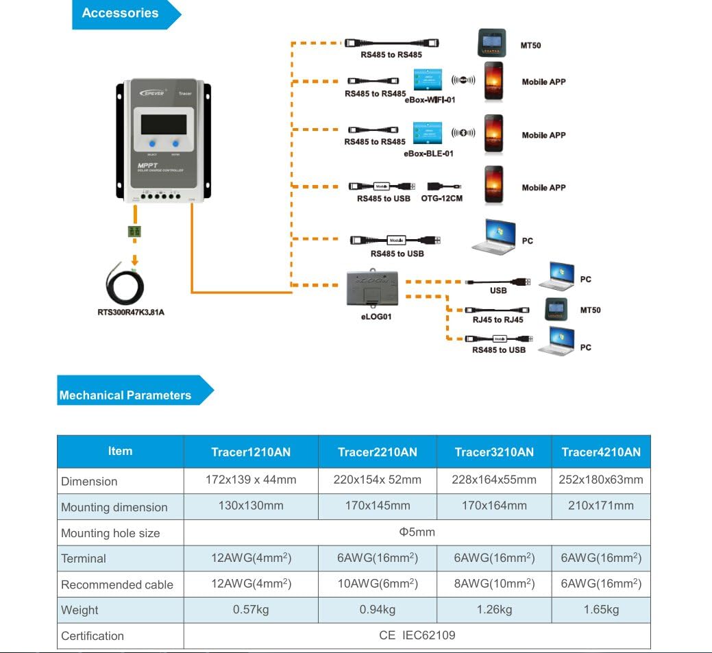
Image 5.2: Diagram showing the EPEVER solar charge controller and its compatible accessories. These include the RTS300R47K3.81A temperature sensor, MT50 remote meter, eBox-WIFI-01, eBox-BLE-01, OTG-12CM, and eLOG01 for various monitoring and communication options.

Image 5.3: The EPEVER Tracer2210AN solar charge controller connected to an MT50 remote meter, displaying system information. This setup allows for convenient monitoring and control.
6. Wartung
Regular maintenance ensures the longevity and optimal performance of your EPEVER solar charge controller:
- Verbindungen prüfen: Periodically inspect all wiring connections for tightness and corrosion. Loose connections can cause voltagTropfenbildung und Überhitzung.
- Controller reinigen: Keep the controller clean and free from dust and debris. Use a dry cloth to wipe the surface. Ensure ventilation openings are not blocked.
- Auf Schäden prüfen: Prüfen Sie, ob der Controller, die Kabel oder die Anschlüsse physische Schäden aufweisen.
- Batterieinspektion: For lead-acid batteries, check electrolyte levels (if applicable) and terminal condition. Ensure lithium batteries are within their recommended operating parameters.
- Umgebungsbedingungen: Stellen Sie sicher, dass die Installationsumgebung innerhalb der vorgegebenen Betriebstemperatur- und Feuchtigkeitsbereiche bleibt.
7. Fehlerbehebung
If you encounter issues with your solar charge controller, refer to the following common troubleshooting steps:
- Kein Display/Stromanschluss:
- Überprüfen Sie die Batterieanschlüsse und stellen Sie sicher, dass die Batteriespannung ausreichend ist.tage liegt innerhalb des Betriebsbereichs des Reglers.
- Verify that the battery fuse (if installed) is intact.
- Keine Aufladung durch Solarpanel:
- Ensure solar panel connections are secure and correct polarity is observed.
- Check the solar panel's open-circuit voltage (Voc) and short-circuit current (Isc) to ensure it is producing power.
- Überprüfen Sie, ob das Solarpanel-Volumentage is within the controller's input voltage Reichweite.
- Check for shading on the solar panels.
- Laden funktioniert nicht:
- Prüfen Sie die Lastanschlüsse und stellen Sie die korrekte Polarität sicher.
- Verify that the battery has sufficient charge. The controller may disconnect the load if the battery voltage ist zu niedrig.
- Check load settings on the controller to ensure the load output is enabled.
- Überhitzung:
- Ensure the controller is installed in a well-ventilated area and its heat sinks are not obstructed.
- Reduce the load or solar input if operating in extreme temperatures.
For more detailed troubleshooting or specific error codes, please refer to the comprehensive manual provided by EPEVER or contact their customer support.
8. Spezifikationen
The following table outlines the key electrical and mechanical parameters for the Tracer2210AN MPPT Solar Charge Controller:

Image 8.1: Table detailing the electrical parameters for Tracer series controllers, including the Tracer2210AN. This table provides specific values for system voltage, currents, power, and environmental conditions.
| Parameter | Value (Tracer2210AN) |
|---|---|
| System-Nennvolumentage | 12V/24V Autobetrieb |
| Nennladestrom | 20 A |
| Nennentladestrom | 20 A |
| Max. PV-Eingangsleistung | 260W (12V Battery System) 520W (24V Battery System) |
| max. PV Leerlauf Voltage | 100V (at min. operating temp) 92V (at 25℃ ambient temp) |
| Batterie Voltage Reichweite | 8 bis 32 V |
| MPP-Voltage Reichweite | V(BAT+2V) ~ 72V |
| Erdung | Gemeinsames Negativ |
| Tracking-Effizienz | ≥99.5 % |
| Max. Umwandlungseffizienz | 98 % |
| Arbeitsumgebungstemperatur | -25℃ ~ +50℃ |
| Lagertemperaturbereich | -20℃ ~ +70℃ |
| Relative Luftfeuchtigkeit | ≤95%, NC |
| Gehäuse | IP30 |
| Abmessungen (L x B x H) | 220 x 154 x 52 mm |
| Gewicht | 0.94 kg |
| Anschlussgröße | #6 AWG (16 mm²) |
| Empfohlenes Kabel | #10 AWG (6 mm²) |
9. Garantie und Support
For warranty information, please refer to the documentation provided with your purchase or contact your authorized EPEVER dealer. EPEVER products typically come with a manufacturer's warranty covering defects in materials and workmanship.
For technical support, product inquiries, or service, please visit the official EPEVER website or contact an authorized EPEVER service center. Ensure you have your product model (Tracer2210AN) and serial number available when seeking support.