
1. Einleitung
The MASTECH MS8260E is a versatile 2000-count digital multimeter designed for a wide range of electrical and electronic measurements. It features a large LCD display, non-contact voltage (NCV)-Erkennung und Fähigkeiten zur Messung von AC/DC-Spannungentage, AC/DC current, resistance, capacitance, and inductance. This manual provides essential information for the safe and effective operation, maintenance, and troubleshooting of your device.
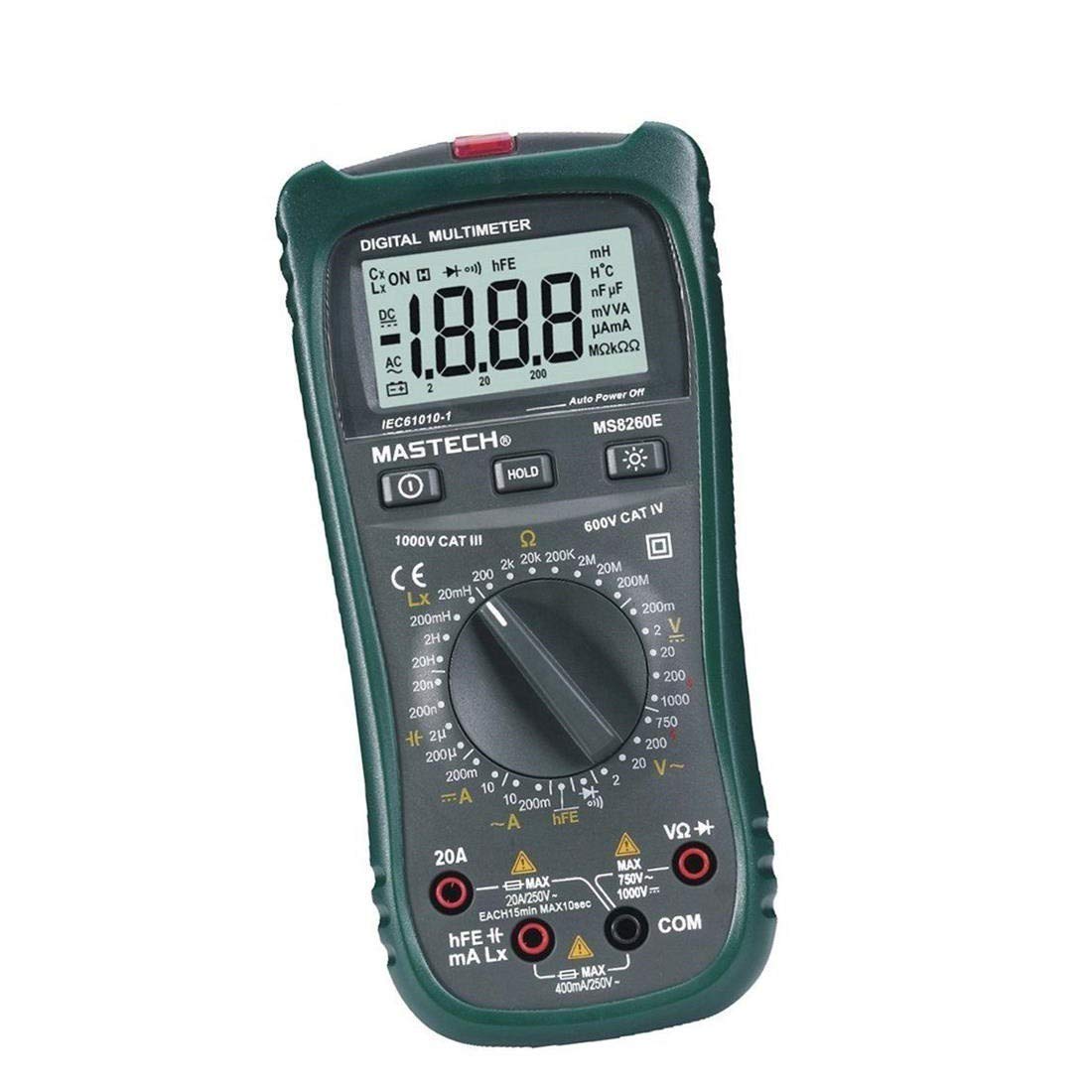
Abbildung 1: Vorderseite view of the MASTECH MS8260E Digital Multimeter, showing the LCD display, function rotary switch, and input jacks.
2. Sicherheitshinweise
To ensure safe operation and service of the meter, follow these safety guidelines:
- Read and understand all instructions in this manual before using the meter.
- Halten Sie sich stets an die örtlichen und nationalen Sicherheitsvorschriften.
- Verwenden Sie das Messgerät nicht, wenn es beschädigt erscheint oder die Isolierung der Messleitungen beschädigt ist.
- Observe the input limits for each measurement range to prevent electrical shock or damage to the meter. This meter is rated for CAT.IV 600V.
- Seien Sie vorsichtig beim Arbeiten mit VolumentagEs liegt über 30 V AC RMS, 42 V Spitze oder 60 V DC. Diese SpannungentagEs besteht die Gefahr eines Stromschlags.
- Trennen Sie den Stromkreis immer vom Stromnetz und entladen Sie alle Hochspannungskondensatoren.tage capacitors before making resistance, continuity, diode, or capacitance measurements.
- Tauschen Sie die Batterie sofort aus, sobald die Anzeige für niedrigen Batteriestand erscheint, um genaue Messwerte zu gewährleisten.
- Das Messgerät darf nicht in explosionsgefährdeten Bereichen mit Gasen, Dämpfen oder Stäuben betrieben werden.
3. Produktüberschreitungview
The MS8260E multimeter is equipped with several features to facilitate accurate and convenient measurements:
- Large 2000 Counts LCD Display: Liefert klare digitale Messwerte.
- Eingebaute berührungslose Lautstärketage (NCV) Detektor: Erkennt AC-Voltage greater than 110V without physical contact, indicated by a flash warning.
- Datenhaltefunktion: Friert den angezeigten Messwert zur einfacheren Aufzeichnung ein.
- Display-Hintergrundbeleuchtung: Improves visibility in dimly lit conditions.
- Automatisches Ausschalten: Conserves battery life by automatically turning off the meter after a period of inactivity.
- Anzeige für niedrigen Batteriestand: Alerts the user when the battery needs replacement.
- Polaritätsanzeige: Automatically displays negative polarity.
- 30-Range Rotary Switch: Selects various measurement functions including AC/DC voltage, AC/DC current, resistance, capacitance, inductance, diode check, continuity test, and transistor (hFE) check.
4. Einrichtung
4.1 Einlegen der Batterie
The MS8260E requires one 9V battery (NEDA 1604/6F22). To install or replace the battery:
- Ensure the meter is turned off and disconnect all test leads from the input terminals.
- Suchen Sie den Batteriefachdeckel auf der Rückseite des Messgeräts.
- Die Befestigungsschraube(n) lösen und die Abdeckung abnehmen.
- Legen Sie die 9V-Batterie unter Beachtung der richtigen Polarität ein.
- Bringen Sie die Abdeckung des Batteriefachs wieder an und befestigen Sie sie mit der/den Schraube(n).
4.2 Anschließen der Testleitungen
Always connect the black test lead to the "COM" (common) input jack. Connect the red test lead to the appropriate input jack based on the desired measurement:
- Für Bdtage, Resistance, Capacitance, Inductance, Diode, Continuity, and hFE measurements: Connect the red lead to the "VΩCAPHz" jack.
- For Current measurements up to 200mA: Connect the red lead to the "mA" jack.
- Für Strommessungen bis 10 A: Schließen Sie die rote Messleitung an die Buchse „10A“ an.
Ensure test leads are fully inserted into the jacks before taking measurements.
5. Bedienungsanleitung
Turn the rotary switch to the desired function. The meter will display "OL" (Overload) if no input is present or if the input exceeds the range.
5.1 DC-Voltage-Messung (DCV)
- Set the rotary switch to the desired DCV range (200mV, 2V, 20V, 200V, 1000V).
- Connect the black test lead to the "COM" jack and the red test lead to the "VΩCAPHz" jack.
- Schließen Sie die Messleitungen an das zu messende Bauteil oder den zu messenden Stromkreis an und achten Sie dabei auf die Polarität.
- Lesen Sie den Bandtage-Wert auf dem LCD-Display.
5.2 AC-Voltage-Messung (ACV)
- Set the rotary switch to the desired ACV range (2V, 20V, 200V, 750V).
- Connect the black test lead to the "COM" jack and the red test lead to the "VΩCAPHz" jack.
- Schließen Sie die Messleitungen an die Wechselstromspannung an.tagDie Quelle.
- Lesen Sie den Bandtage-Wert auf dem LCD-Display.
5.3 Gleichstrommessung (DCA)
- Set the rotary switch to the desired DCA range (200mA, 10A).
- For measurements up to 200mA, connect the red lead to the "mA" jack. For measurements up to 10A, connect the red lead to the "10A" jack. The black lead connects to "COM".
- Öffnen Sie den Stromkreis, in dem der Strom gemessen werden soll, und schließen Sie das Messgerät in Reihe mit der Last an.
- Lesen Sie den aktuellen Wert auf dem LCD-Display ab.
5.4 Wechselstrommessung (ACA)
- Set the rotary switch to the desired ACA range (200mA, 10A).
- For measurements up to 200mA, connect the red lead to the "mA" jack. For measurements up to 10A, connect the red lead to the "10A" jack. The black lead connects to "COM".
- Öffnen Sie den Stromkreis, in dem der Strom gemessen werden soll, und schließen Sie das Messgerät in Reihe mit der Last an.
- Lesen Sie den aktuellen Wert auf dem LCD-Display ab.
5.5 Widerstandsmessung (Ω)
- Set the rotary switch to the desired Ω range (200Ω, 2kΩ, 20kΩ, 200kΩ, 2MΩ, 20MΩ, 200MΩ).
- Connect the black test lead to "COM" and the red test lead to "VΩCAPHz".
- Stellen Sie sicher, dass der Stromkreis stromlos ist und alle Kondensatoren entladen sind.
- Schließen Sie die Messleitungen an den Widerstand oder das Bauteil an.
- Lesen Sie den Widerstandswert auf dem LCD-Display ab.
5.6 Capacitance Measurement (CAP)
- Set the rotary switch to the desired CAP range (20nF, 200nF, 2uF, 200uF).
- Connect the black test lead to "COM" and the red test lead to "VΩCAPHz".
- Stellen Sie sicher, dass der Kondensator vollständig entladen ist, bevor Sie die Messleitungen anschließen.
- Schließen Sie die Messleitungen an den Kondensator an.
- Lesen Sie den Kapazitätswert auf dem LCD-Display ab.
5.7 Induktivitätsmessung (L)
- Set the rotary switch to the desired Inductance range (20mH, 200mH, 2H, 20H).
- Connect the black test lead to "COM" and the red test lead to "VΩCAPHz".
- Schließen Sie die Messleitungen an die Spule an.
- Read the inductance value on the LCD display.
5.8 Diodentest
- Stellen Sie den Drehschalter auf das Diodensymbol.
- Connect the black test lead to "COM" and the red test lead to "VΩCAPHz".
- Schließen Sie die rote Leitung an die Anode und die schwarze Leitung an die Kathode der Diode an. Eine Durchlassspannungtage drop (typically 0.5V to 0.8V for silicon diodes) will be displayed.
- Reverse the leads. The display should show "OL" for a good diode.
5.9 Durchgangstest
- Stellen Sie den Drehschalter auf das Durchgangssymbol.
- Connect the black test lead to "COM" and the red test lead to "VΩCAPHz".
- Schließen Sie die Messleitungen an den Stromkreis oder das Bauteil an.
- Wenn der Widerstand unter etwa 30 Ω liegt, ertönt der Summer, was auf Durchgang hinweist.
5.10 Transistor (hFE) Test
- Stellen Sie den Drehschalter auf die Position hFE.
- Identify the type (NPN or PNP) and pinout (Emitter, Base, Collector) of the transistor.
- Insert the transistor leads into the corresponding sockets in the hFE test socket on the meter.
- Read the hFE (DC current gain) value on the LCD display.
5.11 Berührungslose Voltage (NCV) Erkennung
- Stellen Sie den Drehschalter auf die Position NCV.
- Hold the top front part of the meter near the AC voltage source (e.g., an electrical outlet or insulated wire).
- Wenn AC-Voltage greater than 110V is detected, the NCV indicator light will flash, and the buzzer may sound.
6. Wartung
6.1 Reinigung
Den Zähler mit Werbung abwischenamp Verwenden Sie ein Tuch und ein mildes Reinigungsmittel. Scheuermittel oder Lösungsmittel sind nicht geeignet. Stellen Sie sicher, dass das Messgerät vor Gebrauch trocken ist.
6.2 Batteriewechsel
When the "BAT" symbol appears on the display, the battery needs to be replaced. Refer to Section 4.1 for battery installation instructions.
6.3 Sicherungswechsel
If the current measurement function fails, the fuse may need replacement. This operation should only be performed by qualified personnel. Refer to the service manual or contact customer support for fuse specifications and replacement procedures.
6.4 Speicherung
If the meter is not to be used for an extended period, remove the battery to prevent leakage and damage to the meter. Store the meter in a cool, dry place away from direct sunlight.
7. Fehlerbehebung
| Problem | Mögliche Ursache | Lösung |
|---|---|---|
| Keine oder nur schwache Anzeige | Low battery; Meter off | Replace battery; Turn on meter |
| "OL" angezeigt | Input exceeds range; Open circuit (for resistance/continuity) | Select higher range; Check circuit connection |
| Falsche Messwerte | Low battery; Incorrect range selected; Poor test lead contact | Replace battery; Select appropriate range; Ensure good contact |
| Strommessung funktioniert nicht | Durchgebrannte Sicherung | Replace fuse (by qualified personnel) |
8. Spezifikationen
| Messfunktion | Reichweite | Genauigkeit |
|---|---|---|
| DC-Voltage (DCV) | 200 mV, 2 V, 20 V, 200 V, 1000 V | ±0.5 % (200 mV–200 V), ±0.8 % (1000 V) |
| AC-Lautstärketage (ACV) | 2 V, 20 V, 200 V, 750 V | ±0.8% (2V-200V), ±1.2% (750V) |
| Gleichstrom (DCA) | 200 mA, 10 A | ±1.5% (200mA), ±2.0% (10A) |
| Wechselstrom (ACA) | 200 mA, 10 A | ±1.8% (200mA), ±3.0% (10A) |
| Widerstand (Ω) | 200Ω, 2kΩ, 20kΩ, 200kΩ, 2MΩ, 20MΩ, 200MΩ | ±0.8% (200Ω-2MΩ), ±1.0% (20MΩ), ±5.0% (200MΩ) |
| Kapazität (CAP) | 20 nF, 200 nF, 2 µF, 200 µF | ±4.0% (20nF-2uF), ±5.0% (200uF) |
| Induktivität (L) | 20mH, 200mH, 2H, 20H | ±3.0 % |
| Akustische Kontinuität | Buzzer sounds at <30Ω | N / A |
| Diodentest | 1mA, 2.8V | N / A |
| Transistor (hFE) | 0 - 1,000 | N / A |
Allgemeine Spezifikationen:
- Anzeige: LCD mit 2000 Zählern
- Sicherheitsbewertung: CAT.IV 600V
- Leistung: 9V battery (NEDA 1604/6F22)
- Gewicht: Approximately 1 kg (including battery)
9. Garantie und Support
For warranty information, technical support, or service inquiries, please refer to the warranty card included with your product or visit the official Mastech website. Do not attempt to repair the meter yourself, as this may void the warranty and pose safety risks.