
1. Einleitung
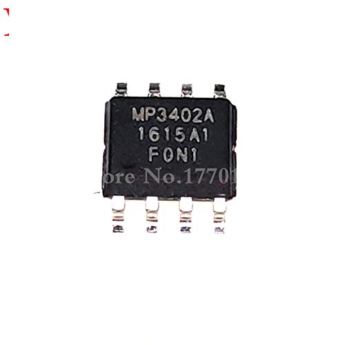
This manual provides essential information for the proper use and integration of the ProIcWorld MP3402/MP3402A DC-DC converter. The MP3402/MP3402A is a compact, high-efficiency step-up (boost) converter designed for applications requiring a regulated output voltage from a lower input voltage source. Its small SOP-8 package makes it suitable for space-constrained designs.
2. Produktbeschreibung
The MP3402/MP3402A is an integrated circuit (IC) designed to efficiently convert a low DC input voltage to a higher, regulated DC output voltage. It incorporates an internal power switch and control circuitry to minimize external component count. This IC is ideal for portable electronic devices, battery-powered systems, and other applications where power efficiency and compact size are critical.
3. Funktionen
- High Efficiency Step-Up (Boost) Converter
- Integrated Power Switch
- Wide Input Voltage Reichweite
- Einstellbare Ausgangsvoltage
- Überstromschutz
- Thermischer Abschaltschutz
- Compact SOP-8 Package
4. Pin-Konfiguration
The MP3402/MP3402A comes in an SOP-8 package. The following table describes the function of each pin:
| Pin Nr. | Name | Beschreibung |
|---|---|---|
| 1 | SW | Switch Node. Connects to the inductor and output diode. |
| 2 | Masse | Ground. Connect to the system ground. |
| 3 | FB | Feedback Pin. Connect to the output voltage Teiler. |
| 4 | COMP | Compensation Pin. Connect RC network for loop stability. |
| 5 | EN | Enable Pin. High for operation, Low for shutdown. |
| 6 | Fahrgestellnummer | Eingangslautstärketage Supply. |
| 7 | Fahrgestellnummer | Eingangslautstärketage Supply. |
| 8 | SW | Switch Node. Connects to the inductor and output diode. |
5. Spezifikationen
Key electrical characteristics and operating parameters:
| Parameter | Wert | Einheit |
|---|---|---|
| Eingangslautstärketage Reichweite | 2.5 bis 5.5 | V |
| Switch Current Limit | Bis zu 2 | A |
| Schaltfrequenz | Bis zu 1.2 | MHz |
| Ruhestrom | Niedrig | µA |
| Betriebstemperaturbereich | -40 bis +85 | °C |
6. Einrichtung und Integration
Integrating the MP3402/MP3402A into a circuit requires careful attention to component selection and PCB layout for optimal performance and stability.
6.1. Component Selection
- Induktor: Select an inductor with appropriate saturation current and low DC resistance.
- Ausgangskondensator: Use low ESR ceramic capacitors for stable output voltage.
- Eingangskondensator: A ceramic capacitor at the input helps filter input ripple.
- Feedback Resistors: Precision resistors are recommended for accurate output voltage Einstellung.
- Diode: A Schottky diode is recommended for the output rectifier due to its low forward voltage fallen.
6.2. Richtlinien für das PCB-Layout
- Keep power traces (VIN, SW, GND) short and wide to minimize parasitic inductance and resistance.
- Place input and output capacitors as close as possible to the IC pins.
- Ensure a solid ground plane for thermal dissipation and noise reduction.
- Route the feedback trace (FB) away from noisy switching nodes to prevent interference.
7. Funktionsprinzipien
The MP3402/MP3402A operates as a boost converter, storing energy in an inductor during the switch ON-time and releasing it to the output during the switch OFF-time. The feedback pin (FB) monitors the output voltage, and the internal control loop adjusts the duty cycle of the internal power switch to maintain a constant output voltage, even with varying input voltage or load conditions.
8. Wartung
As an integrated circuit, the MP3402/MP3402A requires no routine maintenance. Ensure that the operating environment remains within the specified temperature and humidity ranges to prevent damage or degradation of performance. Avoid physical stress or electrostatic discharge (ESD) during handling and assembly.
9. Fehlerbehebung
If the MP3402/MP3402A circuit is not functioning as expected, consider the following troubleshooting steps:
- Keine Ausgangsvoltage:
- Überprüfen Sie die Eingabelautstärketage (VIN) is within the specified range.
- Check if the Enable (EN) pin is pulled high.
- Inspect all solder joints and component connections for continuity.
- Ensure the output diode is correctly oriented and functional.
- Instabile Ausgangslautstärketage:
- Check the values and ESR of input and output capacitors.
- Verify the feedback resistor network for correct values and connections.
- Review PCB layout for excessive noise or long traces, especially on the feedback path.
- Überhitzung:
- Ensure the load current does not exceed the IC's capabilities.
- Prüfen Sie den Ausgang auf Kurzschlüsse.
- Verify proper thermal dissipation through the PCB ground plane.
10. Garantie und Support
As a component, the MP3402/MP3402A is typically covered by the warranty provided by the distributor or seller at the point of purchase. For specific warranty terms, please refer to the purchase agreement or contact your supplier, ProIcWorld. Technical support for integration and application-specific questions may be available through the original component manufacturer's datasheets and application notes, or from your component supplier.
For further assistance, please contact your point of purchase or refer to the official datasheets for the MP3402/MP3402A series.