1. Einleitung
This manual provides essential information for the safe and efficient operation of your Mastervolt Mass 24/50-2 battery charger. The Mass 24/50-2 is a robust 24 V battery charger designed for demanding marine and industrial applications. It delivers up to 50 A of total charging current and features two battery outputs for managing multiple battery banks. The unit incorporates automatic multi-stage charging and comprehensive protection mechanisms to ensure reliable and efficient power support.
2. Sicherheitshinweise
Lesen Sie vor Installation und Inbetriebnahme alle Sicherheitshinweise sorgfältig durch. Die Nichtbeachtung dieser Hinweise kann zu Stromschlag, Brand oder schweren Verletzungen führen.
- Always disconnect the AC power supply before performing any installation, maintenance, or troubleshooting.
- Sorgen Sie für ausreichende Belüftung rund um das Ladegerät, um eine Überhitzung zu vermeiden.
- Do not expose the charger to rain, moisture, or excessive dust.
- Beim Umgang mit Batterien und elektrischen Systemen ist geeignete persönliche Schutzausrüstung (PSA) zu verwenden.
- Ensure all electrical connections are tight and secure to prevent arcing and overheating.
- This device is designed for use with 24V battery systems only. Do not connect to other voltage-Systeme.
- Keep children and unauthorized personnel away from the charger and battery area.
3. Produktüberschreitungview
The Mastervolt Mass 24/50-2 battery charger features a durable construction suitable for harsh environments. Key components include power terminals, communication ports, and configuration switches.
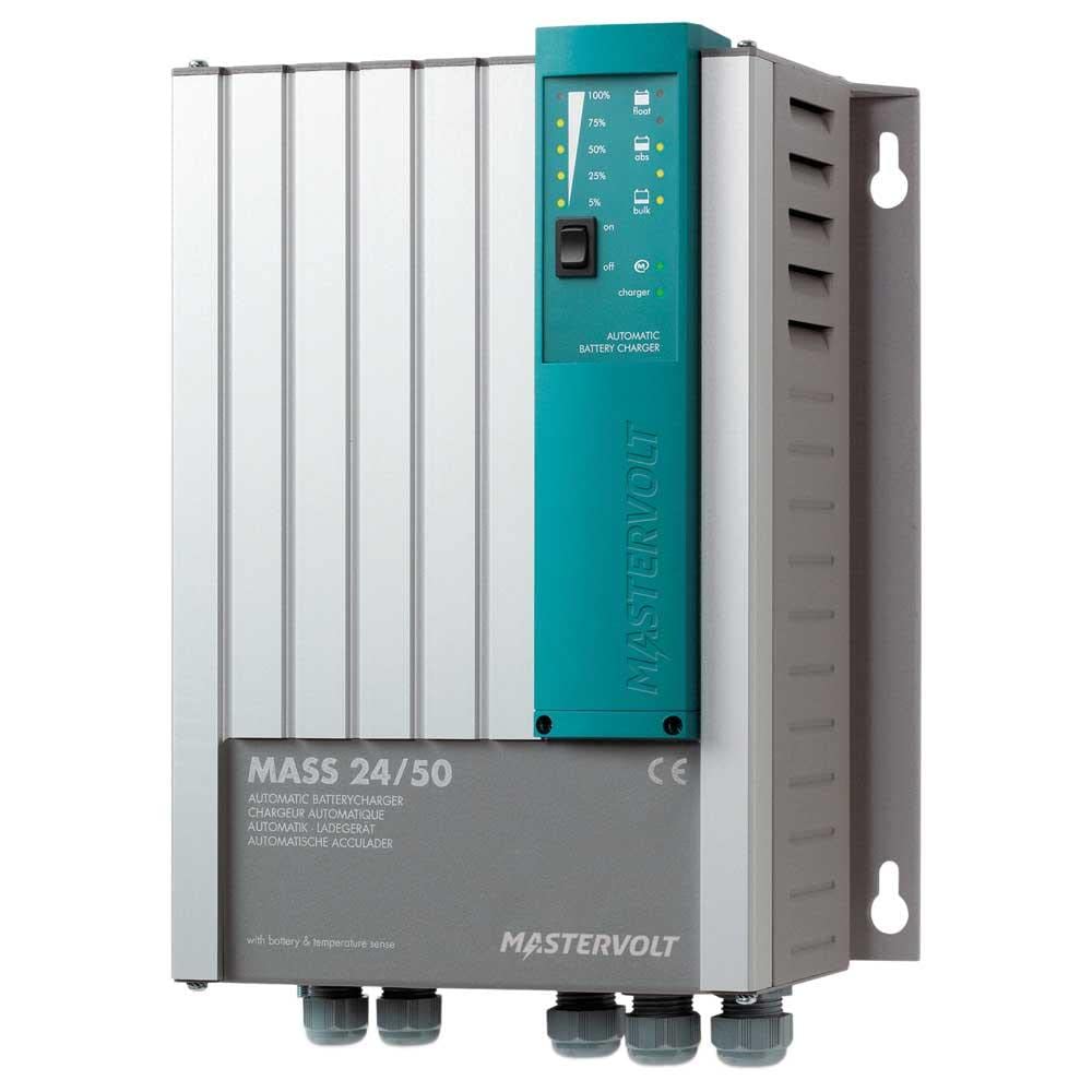
Figure 1: Connection Panel of the Mastervolt Mass 24/50-2
This image displays the various connection points on the Mastervolt Mass 24/50-2. Visible are the DIP switches labeled '4321' for configuration, RJ45 ports for 'RS485', 'RS232', 'ANALOG', and 'TEMP.SENSOR' communication, and a green terminal block for remote sensing or control labeled '+S', '-S', 'NO', 'C', 'NC'. Additionally, a '+3A' terminal and two large screw terminals for main power connections are shown.
Hauptmerkmale:
- 24 V Ausgangsspannungtage.
- 50 A total charging current.
- Two independent battery outputs.
- Automatische MultistagE-Laden für optimale Batterielebensdauer.
- Robust design for marine and industrial use.
- Integrated protections against overvoltage, Überstrom und Kurzschlüsse.
- Communication interfaces: RS485, RS232, Analog, Temperature Sensor input.
4. Einrichtung
4.1. Montage
Mount the charger in a dry, well-ventilated area, away from direct sunlight and heat sources. Ensure sufficient clearance around the unit for airflow. The charger is designed to be waterproof and shakeproof, making it suitable for challenging environments, but proper mounting is still crucial for optimal performance and longevity.
4.2. Elektrische Anschlüsse
- Batterieanschlüsse: Connect the main battery bank to the large screw terminals marked with '+' and '-' symbols. Ensure correct polarity. If using the second output, connect the secondary battery bank as per the wiring diagram in the full product manual.
- AC-Eingang: Connect the AC power supply cable to the designated AC input terminals. Ensure the AC supply matches the charger's input voltage-Anforderungen.
- Temperatursensor: Connect the optional temperature sensor to the 'TEMP.SENSOR' port. This allows the charger to adjust charging voltage based on battery temperature, optimizing charging and extending battery life.
- Remote Sensing/Control: Utilize the green terminal block ('+S', '-S', 'NO', 'C', 'NC') for remote voltage sensing or control functions as required by your system setup. Refer to the detailed wiring diagrams for specific applications.
- Kommunikationsanschlüsse: Connect RS485 or RS232 communication cables to the respective RJ45 ports for integration with monitoring systems or other Mastervolt devices.
- Dip-Schalter: The DIP switches labeled '4321' are used for configuring specific charger settings, such as battery type or charging profile. Consult the comprehensive product manual for detailed instructions on DIP switch settings relevant to your battery type and application.
5. Betrieb
The Mastervolt Mass 24/50-2 operates automatically once properly installed and powered. It employs an advanced multi-stage charging process to ensure batteries are charged efficiently and safely.
- Einschalten: After all connections are secure, apply AC power to the charger. The charger will initiate its startup sequence.
- Aufladen Stages: The charger automatically progresses through various charging stages (e.g., bulk, absorption, float) to optimize battery charging.
- Überwachung: Monitor the charger's status indicators (if present, refer to the full manual for indicator descriptions) or connected monitoring systems for charging status and battery health.
6. Wartung
Regular maintenance ensures the longevity and optimal performance of your Mastervolt Mass 24/50-2 charger.
- Reinigung: Reinigen Sie die Außenseite des Ladegeräts regelmäßig mit einem trockenen, weichen Tuch. Verwenden Sie keine Scheuermittel oder Lösungsmittel. Achten Sie darauf, dass die Lüftungsöffnungen frei von Staub und Schmutz sind.
- Verbindungsprüfungen: Annually, or more frequently in harsh environments, inspect all electrical connections for tightness and corrosion. Tighten any loose connections.
- Batterieinspektion: Regularly inspect your batteries for signs of damage, corrosion, or electrolyte leakage. Follow battery manufacturer's maintenance guidelines.
7. Fehlerbehebung
If you encounter issues with your Mastervolt Mass 24/50-2, refer to the following basic troubleshooting steps. For complex problems, consult the full product manual or contact Mastervolt support.
- Ladegerät schaltet sich nicht ein: Check the AC power supply, circuit breakers, and all AC input connections.
- Kein Ladeausgang: Verify battery connections and polarity. Ensure the charger is receiving AC input. Check for any error indicators on the unit.
- Überhitzung: Ensure adequate ventilation around the charger. Clear any obstructions from cooling vents. Reduce load if possible.
- Ungewöhnliche Geräusche oder Gerüche: Immediately disconnect power and contact qualified service personnel.
8. Spezifikationen
| Spezifikation | Wert |
|---|---|
| Marke | Mastervolt |
| Modellnummer | 40020506 |
| Ausgangsvolumentage | 24 V |
| Ladestrom | 50 A |
| Anzahl der Ausgänge | 2 |
| Material | Plastik |
| Artikelgewicht | 8.4 Pfund (3.8 kg) |
| Produktabmessungen (L x B) | 18 Zoll lang x 14 Zoll breit (45.7 cm x 35.6 cm) |
| Besondere Merkmale | Waterproof, Shakeproof |
| Montagetyp | Tabletop Mount (can be adapted for other mounts) |
| UPC | 852968002745 |
9. Garantie und Support
The Mastervolt Mass 24/50-2 comes with a manufacturer's warranty. For specific warranty terms and conditions, please refer to the warranty documentation included with your product or visit the official Mastervolt website. For technical support, service, or further inquiries, please contact Mastervolt customer service or your authorized dealer.