
1. Produktüberschreitungview
The Walfront Single Phase Voltage Protector and Energy Meter is a multi-functional device designed to protect electrical circuits from overvoltage, Untervoltage, and overcurrent conditions. It features an auto-recovery function, automatically restoring power once fault conditions return to normal. The integrated display provides real-time voltage-, Strom- und Leistungsmesswerte.
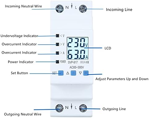
Abbildung 1: Vorderseite view of the Walfront Voltage Protector, highlighting the LCD display, undervoltage, übervoltage, and overcurrent indicators, as well as the 'SET' and adjustment buttons.
Hauptmerkmale:
- Auto-Recovery Function: Automatically restores power after undervoltage or overcurrent faults are resolved.
- Klare Anzeige: LCD shows real-time voltage, Strom und Leistung.
- Mehrfachschutz: Inklusive Übervoltage, Untervoltage und Überstromschutz.
- Anti-Thunder Protection: Enhances device stability and safety.
- Langlebige Konstruktion: Made from high-quality, flame-retardant materials for extended service life.
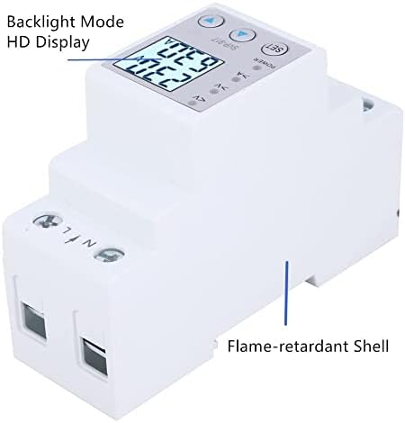
Abbildung 2: Seite view illustrating the flame-retardant shell of the device, contributing to its durability and safety.
2. Einrichtung und Installation
This device is designed for DIN rail mounting in an electrical panel. Proper installation by a qualified electrician is recommended to ensure safety and correct functionality.
2.1 Schaltplan
Connect the incoming neutral wire to the 'N' terminal and the incoming live wire to the 'L' terminal on the top of the device. Connect the outgoing neutral wire to the 'N' terminal and the outgoing live wire to the 'L' terminal on the bottom of the device. Ensure all connections are secure.
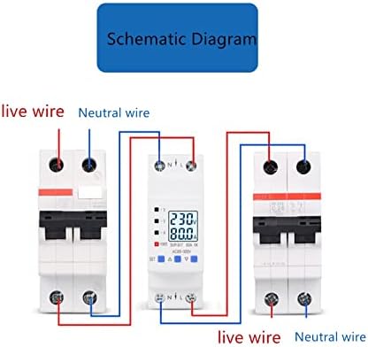
Figure 3: Wiring schematic. The device is installed between an incoming circuit breaker and an outgoing circuit breaker, with live and neutral wires connected to the respective 'L' and 'N' terminals.
2.2 Montage
The device is designed for standard 35mm DIN rail mounting. Snap the device onto the DIN rail securely within your electrical enclosure.

Figure 4: The device mounted on a DIN rail within an electrical panel, demonstrating a typical installation scenario.
3. Bedienungsanleitung
Upon successful installation and power-up, the LCD will display real-time voltage and current. Use the 'SET' button and the up/down arrow buttons to navigate and adjust settings.
3.1 Displayanzeigen
- <V: Untervoltage Indikator.
- >V: Übervolumentage Indikator.
- >A: Overcurrent indicator.
- LEISTUNG: Betriebsanzeige.
- Anzeigegerät: Zeigt voltage (V), Strom (A) und Leistung (W).
3.2 Menu Settings and Parameters
Press the 'SET' button to enter the menu. Use the up (▲) and down (▼) arrow buttons to navigate through the settings and adjust values. Press 'SET' again to confirm a selection or value.
- DE (Device Mode): Controls the operational mode of the device.
- DE1: Übervolumentage, Untervoltage, and overcurrent protection with automatic switch off/on.
- DE2: Übervolumentage, Untervoltage, and overcurrent protection with automatic switch off/manual switch on.
- DE3: Übervolumentage, Untervoltage, and overcurrent protection disabled; output load switch remains off.
- DE4: Übervolumentage, Untervoltage, and overcurrent protection disabled; output load switch remains on.
- DE5: Übervolumentage, Untervoltage, and overcurrent protection disabled; output load switch cycles on/off (unit: seconds).
- Bg (Backlight Mode):
- Modus 1: Backlight always on.
- Modus 2: Backlight illuminates for 30 seconds after a button is pressed.
- SS (Start-up Delay): Delay time for load switch-on after input power is applied.
- Uo (Overvoltage Protection Value): Legt die obere Lautstärke festtage Grenze.
- UoH (Overvoltage Recovery Value): Stellt die Lautstärke eintage at which the device recovers after an overvoltagDas Ereignis.
- UL (Undervoltage Protection Value): Stellt die untere Lautstärke eintage Grenze.
- ULH (Undervoltage Recovery Value): Stellt die Lautstärke eintage at which the device recovers after an undervoltagDas Ereignis.
- SU (Voltage Fault Judgment Time): Time duration for judging overvoltage/Untervoltage Fehler.
- Io (Overcurrent Protection Value): Sets the upper current limit.
- Ic (Malignant Load Protection Value): Pure Resistive Load limit.
- SI (Overcurrent Fault Judgment Time): Time duration for judging overcurrent faults.
- SH (Recovery Delay): Delay time setting for load recovery after an output load switch-off protection event.
- Op (Cycle Switch Off Delay): Delay time set for cycle switch off under function mode 5.
- CL (Cycle Switch On Delay): Delay time set for cycle switch on under function mode 5.
- Er1 (Error Records): Displays the last five records of protection reasons.
4. Wartung
The Walfront Voltage Protector is designed for minimal maintenance. However, regular checks can ensure optimal performance and longevity.
- Reinigung: Halten Sie das Gerät sauber und staubfrei. Verwenden Sie zum Reinigen ein trockenes, weiches Tuch. Verwenden Sie keine flüssigen Reinigungsmittel.
- Verbindungsprüfungen: Periodically inspect wiring connections to ensure they remain tight and free from corrosion. Loose connections can lead to overheating or intermittent operation.
- Umgebungsbedingungen: Um Schäden zu vermeiden, muss sichergestellt werden, dass das Gerät innerhalb der spezifizierten Umgebungsbedingungen (Temperatur, Luftfeuchtigkeit) betrieben wird.
5. Fehlerbehebung
If you encounter issues with your Walfront Voltage Protector, refer to the following common troubleshooting steps:
- Gerät lässt sich nicht einschalten:
- Überprüfen Sie die Stromversorgung.
- Prüfen Sie, ob alle Kabelverbindungen korrekt und fest sind.
- Ensure the main circuit breaker supplying the device is ON.
- Keine Ausgangsleistung:
- Check the display for active protection indicators (<V, >V, >A). If active, resolve the underlying voltage or current issue.
- Review the 'DE' (Device Mode) setting. Ensure it is not set to DE3 (output off) or DE5 (cycling).
- If in DE2 mode, a manual reset might be required after a fault.
- Check 'Er1' for recent protection reasons.
- Falsche Messwerte:
- Ensure the device is correctly wired and that the load is within its specified limits.
- Verify the device is the correct amperage (e.g., 80A model).
- Einstellungen werden nicht gespeichert:
- Ensure you press the 'SET' button to confirm changes after adjusting a parameter.
6. Spezifikationen
| Spezifikation | Wert |
|---|---|
| Marke | Walfront |
| Modell | me791gt8nu-12 |
| Aktuelle Bewertung | 80 Amps |
| Leistungsschaltertyp | Standard |
| Montagetyp | DIN-Schienenmontage |
| Anzahl der Pole | 1 |
| Bandtage | Wechselstrom 85-300 Volt |
6.1 Abmessungen

Figure 5: Device dimensions, including front and side views with measurements in centimeters.
6.2 verfügbare Modelle
The Walfront Voltage Protector is available in different current ratings.

Figure 6: Optional styles available, including 63A and 80A versions of the device.
7. Garantieinformationen
Walfront products are manufactured to high-quality standards. For specific warranty details, please refer to the product packaging or contact Walfront customer support. Typically, a limited warranty covers defects in materials and workmanship under normal use.
8. Kundendienst
For technical assistance, troubleshooting, or inquiries regarding your Walfront Voltage Protector, please visit the Walfront store on Amazon or contact their customer service directly. Contact information can usually be found on the product packaging or the official Walfront brand page.
Walfront Store Link: Visit the Walfront Store on Amazon