1. Einleitung
Thank you for choosing the TIC-D2500 2-Input, 2-Zone, 2X300W Bridged Power Amplifier. Diese professionelle Qualität amplifier is designed for reliable performance in various audio applications, featuring 8 Ohm, 4 Ohm, and 70V output capabilities, along with Crown ultra-efficient DriveCore technology. This manual provides essential information for the safe and efficient operation of your ampschwerer.
2. Sicherheitshinweise
WARNUNG: To reduce the risk of fire or electric shock, do not expose this equipment to rain or moisture. Do not open the casing. Alle Wartungsarbeiten sind von qualifiziertem Servicepersonal durchführen zu lassen.
- Lesen Sie alle Anweisungen vor der Inbetriebnahme des ampschwerer.
- Bewahren Sie diese Anleitung zum späteren Nachschlagen auf.
- Beachten Sie alle Warnhinweise auf dem Produkt und in der Bedienungsanleitung.
- Befolgen Sie alle Anweisungen.
- Verwenden Sie dieses Gerät nicht in der Nähe von Wasser.
- Nur mit trockenem Tuch reinigen.
- Die Lüftungsöffnungen dürfen nicht blockiert werden. Die Installation muss gemäß den Anweisungen des Herstellers erfolgen.
- Installieren Sie das Gerät nicht in der Nähe von Wärmequellen wie Heizkörpern, Heizregistern, Öfen oder anderen Geräten (einschließlich ampKonverter (Lüfter), die Wärme erzeugen.
- Machen Sie den Sicherheitszweck des polarisierten oder geerdeten Steckers nicht zunichte. Ein polarisierter Stecker hat zwei Stifte, von denen einer breiter als der andere ist. Ein geerdeter Stecker hat zwei Stifte und einen dritten Erdungsstift. Der breite Stift oder der dritte Stift dienen Ihrer Sicherheit. Wenn der mitgelieferte Stecker nicht in Ihre Steckdose passt, wenden Sie sich an einen Elektriker, um die veraltete Steckdose auszutauschen.
- Schützen Sie das Netzkabel vor Beschädigungen oder Beschädigungen durch Fußgänger, insbesondere an den Steckern, Steckdosen und an der Stelle, an der es aus dem Gerät austritt.
- Verwenden Sie nur vom Hersteller angegebene Zusatzgeräte/Zubehör.
- Trennen Sie das Gerät bei Gewitter oder längerer Nichtbenutzung vom Stromnetz.
- Überlassen Sie alle Wartungsarbeiten qualifiziertem Servicepersonal. Eine Wartung ist erforderlich, wenn das Gerät auf irgendeine Weise beschädigt wurde, z. B. wenn das Netzkabel oder der Stecker beschädigt sind, Flüssigkeit in das Gerät verschüttet wurde oder Gegenstände hineingefallen sind, das Gerät Regen oder Feuchtigkeit ausgesetzt war, nicht normal funktioniert oder fallengelassen wurde.
3. Produktüberschreitungview
3.1 Frontplatte

Figure 3.1: Front Panel of the TIC-D2500 Amplifier. Shows the power switch, LCD display, control knobs for channels A and B, and navigation buttons.
- Stromschalter: Schaltet den amplifier ein oder aus.
- CHA / CHB Level Controls: Rotary knobs to adjust the output level for Channel A and Channel B independently.
- LCD Anzeige: Shows volume in dB per channel, operating temperature, and other system information.
- Navigation Buttons (Home, Level, Type, Function, Mute): Dient zur Navigation in Menüs und zur Anpassung von Einstellungen auf dem LCD-Display.
- TIC-D2500 Model Indicator: Displays the product model number.
3.2 Rückseite

Figure 3.2: Rear Panel of the TIC-D2500 Amplifier. Displays input/output connectors, mode switches, AC inlet, and breaker.
- Unterbrecher: Circuit breaker for protection.
- AC-Eingang: Power input connector for the AC power cord.
- Speaker Outputs (CH1, CH2, BRG): Connectors for speaker cables. Supports 4Ω, 8Ω, and 70V outputs. Includes both binding posts and Speakon-style connectors.
- CH1 Input / CH2 Input (XLR): Balanced XLR input connectors for audio signals.
- CH1 Link / CH2 Link (XLR): XLR link outputs for passing the input signal to another amplifier or device.
- Mode Switches (BRG, PARALLEL, STEREO): Switches to select the amplifier's operating mode (Bridged, Parallel, or Stereo).
- HI-PASS Switches (OFF, 30Hz, 50Hz): Switches to activate high-pass filters at 30Hz or 50Hz, or disable them.
3.3 Detailed Rear Panel Connectors
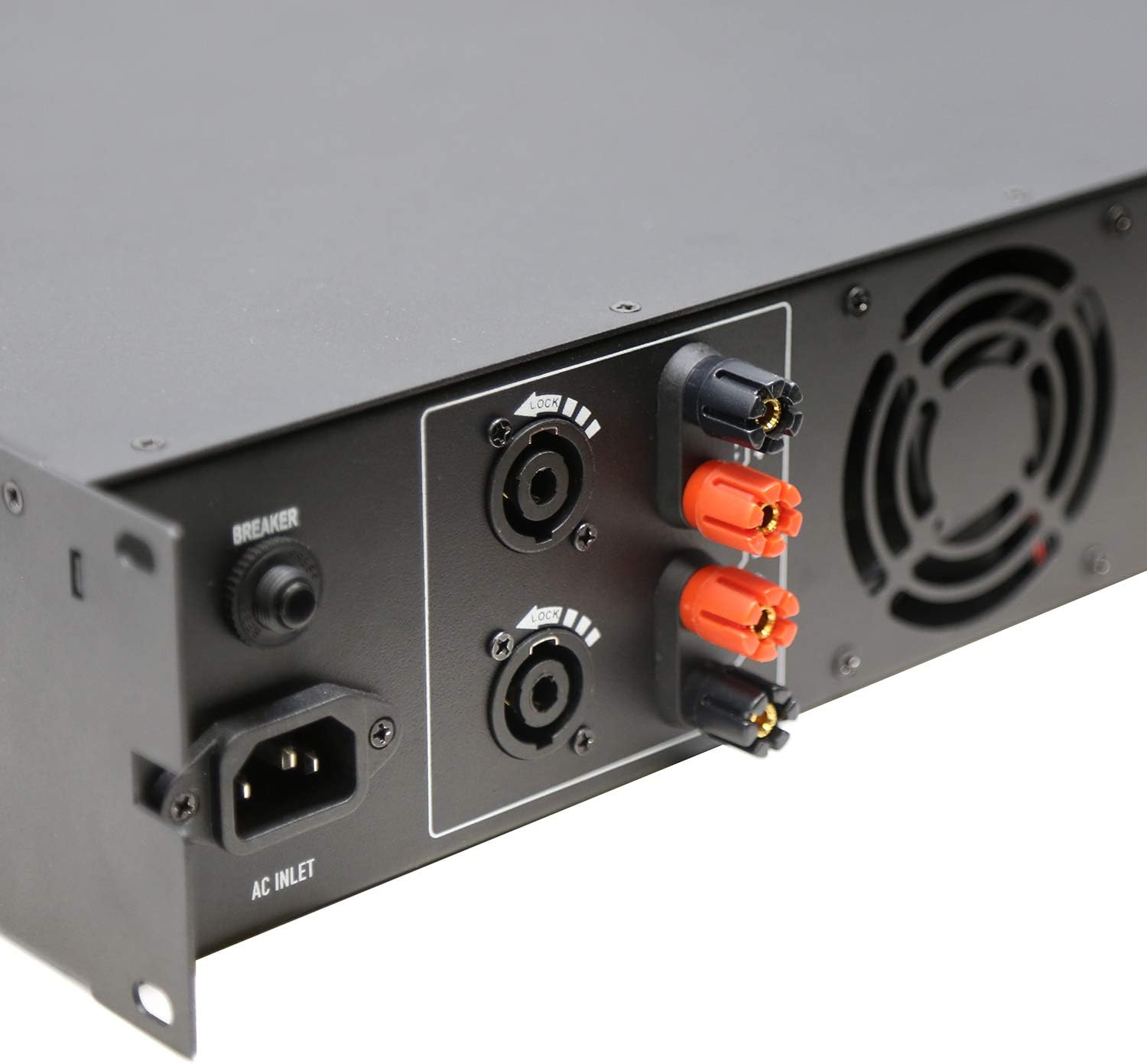
Figure 3.3: Rear Left Panel Detail. Shows the AC inlet, breaker, and speaker output terminals (binding posts and Speakon).

Figure 3.4: Rear Right Panel Detail. Shows the XLR input and link output connectors, along with the BRG/PARALLEL/STEREO and HI-PASS switches.
4. Einrichtung
- Platzierung: Stellen Sie sicher, dass amplifier is placed in a well-ventilated area, preferably in a standard 2U rack space. Maintain adequate clearance around the unit for airflow.
- Stromanschluss:
- Stellen Sie sicher, dass ampDer Netzschalter des Verstärkers befindet sich in der Position AUS.
- Connect the supplied AC power cord to the AC Inlet on the rear panel and then to a suitable grounded power outlet.
- Eingangsanschlüsse:
- Schließen Sie Ihre Audioquelle (Mixer, Vorverstärker) an.amplifier, etc.) to the CH1 INPUT and CH2 INPUT XLR connectors on the rear panel using balanced XLR cables.
- If linking to another amplifier, use the CH1 LINK and CH2 LINK XLR outputs.
- Output Connections (Speakers):
- Connect your speakers to the appropriate speaker output terminals (binding posts or Speakon) on the rear panel. Ensure correct polarity (+ to + and - to -).
- For 70V systems, ensure your speakers are compatible with 70V constant voltage systems and connect them accordingly.
- For 4Ω or 8Ω operation, ensure your speakers' impedance matches the amplifier's output capabilities for the selected mode (Stereo or Parallel).
- For Bridged mode (BRG), connect a single speaker to the designated BRG output terminals. Refer to the rear panel markings for correct connections.
- Modusauswahl:
- Set the BRG/PARALLEL/STEREO switch to your desired operating mode.
- Set the HI-PASS switches according to your system requirements. "OFF" for full range, "30Hz" or "50Hz" to filter out low frequencies.
5. Bedienungsanleitung
- Einschalten:
- Before powering on, ensure all level controls (CHA, CHB) are set to their minimum position.
- Schalten Sie zuerst Ihr Audiogerät ein.
- Flip the Power Switch on the front panel to the ON position. The LCD display will illuminate.
- Lautstärke anpassen:
- Slowly increase the CHA and CHB level controls to achieve the desired output volume.
- Monitor the LCD display for volume levels (in dB) and operating temperature.
- Using the LCD Display and Navigation:
- Use the "Home", "Level", "Type", "Function", and "Mute" buttons to navigate through the amplifier's settings and monitoring options displayed on the LCD.
- Consult the on-screen menus for specific adjustments related to input sensitivity, output modes, and other advanced features.
- Ausschalten:
- Before powering off, reduce all level controls to their minimum position.
- Schalten Sie den ampNetzschalter ein.
- Turn off your audio source equipment.
6. Wartung
- Reinigung: Trennen Sie den amplifier from power before cleaning. Use a soft, dry cloth to wipe down the exterior. Do not use liquid cleaners or aerosols.
- Belüftung: Regularly check that ventilation openings are clear of dust and debris to ensure proper cooling.
- Kabelverbindungen: Periodically inspect all cable connections for secure fit and signs of wear.
- Lagerung: Bei der Speicherung der ampWenn Sie den Verstärker über einen längeren Zeitraum verwenden, stellen Sie sicher, dass er an einem kühlen, trockenen Ort steht und vor Staub und extremen Temperaturen geschützt ist.
7. Fehlerbehebung
| Problem | Mögliche Ursache | Lösung |
|---|---|---|
| Kein Strom | Power cord disconnected; Power switch off; Circuit breaker tripped; Power outlet issue. | Check power cord connection; Ensure power switch is ON; Reset circuit breaker; Test power outlet with another device. |
| Keine Tonausgabe | Input cables disconnected; Speaker cables disconnected or incorrect polarity; Amplifier level controls at minimum; Incorrect mode selection; Audio source issue. | Check all input and output cable connections; Verify speaker polarity; Increase CHA/CHB level controls; Ensure correct BRG/PARALLEL/STEREO mode is selected; Check audio source. |
| Verzerrter Ton | Input signal too high (clipping); Amplifier overloaded; Speaker impedance mismatch; Faulty cables. | Reduce input signal level from source; Ensure speakers match amplifier impedance; Check speaker connections and cables; Reduce amplifier-Ausgangspegel. |
| Überhitzung | Blocked ventilation; Excessive load; Prolonged high-level operation. | Sorgen Sie für ausreichende Belüftung um das amplifier; Reduce load or operating level; Allow ampLassen Sie den Lüfter abkühlen. |
If the problem persists after attempting these solutions, please contact qualified service personnel or TIC Audio support.
8. Spezifikationen
| Besonderheit | Detail |
|---|---|
| Modell | T2500 - Die wunderbare Welt der Träume |
| Output Power (8Ω) | 300 B x 2 |
| Ausgangsimpedanz | 4Ω / 8Ω / 70V Stable |
| Amplifier-Typ | Class D with Crown DriveCore technology |
| Frequenzgang | 20Hz - 20KHz (+/-3dB) |
| Eingangsanschlüsse | 2 x 3-pin XLR (balanced signal input) |
| Ausgangsanschlüsse | Speaker (x2) - Binding Posts & Speakon-style |
| Rack-Platz | 2U |
| Abmessungen (B x T x H) | 483 x 257 x 88.8mm (19 x 10.1 x 3.5 inches approx.) |
| Artikelgewicht | 17.27 Pfund (7.83 kg) |
| Stromquelle | AC |
9. Garantie und Support
For warranty information, technical support, or service inquiries, please contact TIC Audio directly. Refer to the official TIC Audio webDie aktuellsten Kontaktdaten und Garantiebedingungen finden Sie auf unserer Website oder in Ihren Kaufunterlagen.
This product may be eligible for extended protection plans. Please refer to your retailer for details on available protection plans.
Hersteller: TIC Audio