Docooler XUH6362338938855GM
Docooler JINGSHA X99-8D3 Motherboard User Manual
Model: XUH6362338938855GM
1. Einführung und Endeview
The Docooler JINGSHA X99-8D3 is a high-performance ATX gaming motherboard designed for LGA2011 V3 processors. It features four-channel DDR3 memory support, an M.2 NVME slot for high-speed storage, and multiple PCI-E expansion slots, making it suitable for demanding computing tasks and gaming setups. This manual will guide you through the installation, configuration, and maintenance of your motherboard.
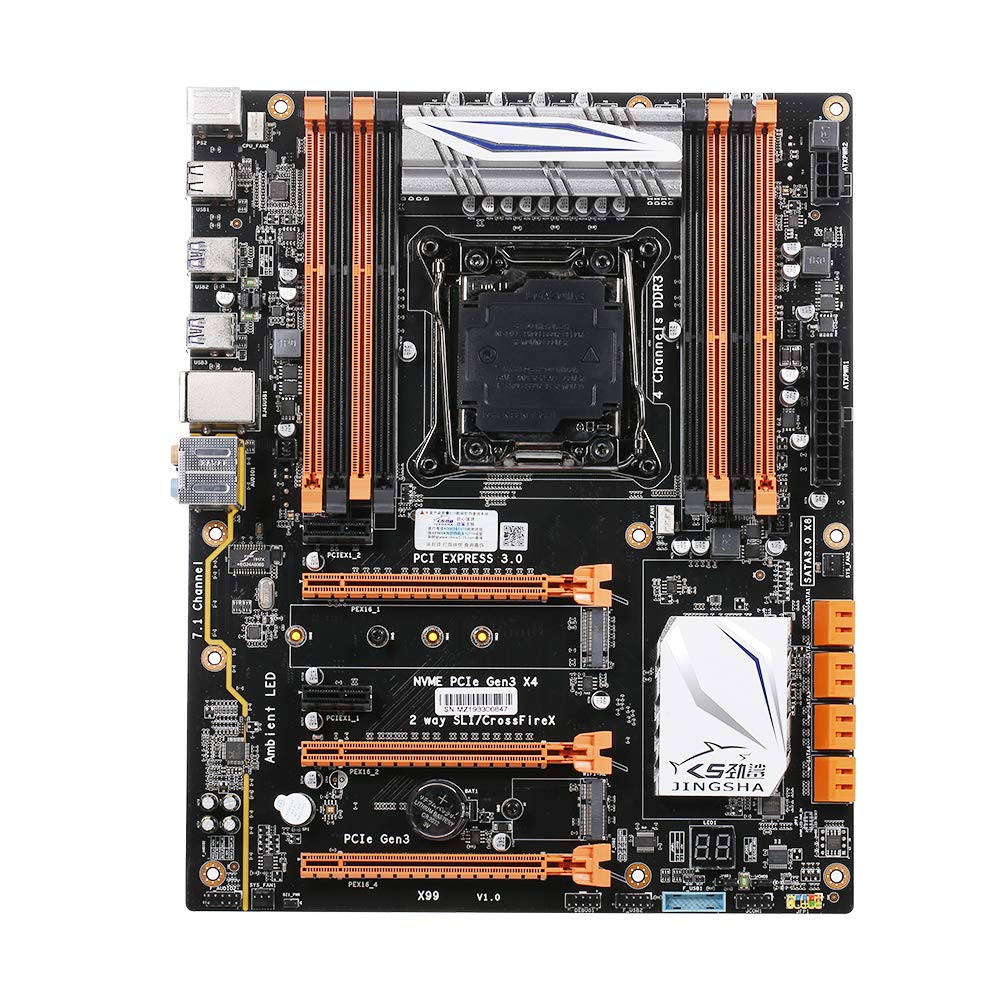
Abbildung 1.1: Draufsicht view of the Docooler JINGSHA X99-8D3 Motherboard, showcasing its layout with CPU socket, RAM slots, and various expansion slots.
2. Hauptmerkmale
- M.2 NVME Support: Equipped with an M.2 hard disk port, supporting high-speed PCI-E NVME X4 for optimal operating system and application driver performance.
- Quad-Channel DDR3 Memory: Features 8 DDR3 memory slots across 4 channels, significantly improving capacity and performance, supporting up to 256GB.
- Digital Diagnostic Card: Integrated digital diagnostic card automatically tests hardware devices to ensure proper operation and assist in troubleshooting.
- Multiple PCI-E Expansion Slots: Provides 3 PCI-E expanded slots, configurable as X16/X8 to handle various workloads and multi-GPU setups.
- Langlebige Konstruktion: Built with a 10-layer PCB and high-quality capacitors for enhanced stability and heat resistance.

Figure 2.1: Diagram illustrating the six core technologies and features of the motherboard, including 4-channel DDR3*8, M.2 hard disk interface, digital diagnostic card, 7.1 channel audio, SATA3.0*8 interface, and Crossfire support.
3. Packungsinhalt
Bitte überprüfen Sie, ob alle unten aufgeführten Artikel in Ihrem Paket enthalten sind:
- 1x Docooler JINGSHA X99-8D3 Motherboard
- 1x SATA-Kabel
- 1x I/O Baffle (Backplate)
- 1x CPU Fan Board
- A bag of screws
4. Spezifikationen
| Besonderheit | Spezifikation |
|---|---|
| Modell | X99-8D3 |
| Formfaktor | ATX |
| Graphic Slot | PCIE3.0 16X*3 |
| Netzwerkkarte | Gigabit-Netzwerkkarte |
| Audiokanal | 7.1 Kanäle |
| CPU Type Support | LGA2011 V3 (2629V3/2649V3/2669V3/2678V3/2696V3/2676V3/2673V3) |
| PCB-Schichten | 10 Schichten |
| Speicherkartensteckplatz | DDR3*8 |
| Maximale Speicherkapazität | 256 GB |
| SATA-Schnittstelle | SATA3.0*8, M.2 NVME |
| PS/2-Schnittstelle | Maus / Tastatur |
| Stromversorgung | 8 PIN*1, 24 PIN*1 |
| USB-Schnittstelle | USB 3.0*6, USB 2.0*6 |
| Erweiterte Schnittstelle | PCIE 1X*2, M.2 WIFI*1 |
| Artikelgröße | 30.2 x 24.4 cm (11.89 x 9.61 Zoll) |
| Artikelgewicht | 930.5 g (32.82 oz) |

Abbildung 4.1: Ausführlich view of the motherboard's rear I/O panel, showing PS/2 ports, USB 2.0, USB 3.0, Gigabit Network Port, and 7.1 Audio Ports.
5. Einrichtung und Installation
Before beginning installation, ensure your system is powered off and unplugged from the wall outlet. Handle the motherboard by its edges to avoid static discharge.
5.1 Einbau der CPU
- Locate the LGA2011 V3 CPU socket on the motherboard.
- Gently push down the CPU retention lever and swing it open.
- Align the triangular mark on your CPU with the corresponding mark on the socket. Carefully place the CPU into the socket without forcing it.
- Schließen Sie den Haltehebel, um die CPU zu sichern.
- Tragen Sie eine dünne, gleichmäßige Schicht Wärmeleitpaste auf die Oberseite der CPU auf.
- Installieren Sie den CPU-Kühler gemäß den Anweisungen des Herstellers und achten Sie dabei auf korrekten Kontakt und Anpressdruck.

Abbildung 5.1: Nahaufnahme view of the LGA2011 V3 CPU socket on the motherboard, ready for CPU installation.
5.2 Einbau von RAM-Modulen
- Öffnen Sie die Klemmen an beiden Enden der DDR3-Speichersteckplätze.
- Richten Sie die Kerbe am RAM-Modul an der Kerbe im Speicherslot aus.
- Drücken Sie beide Enden des RAM-Moduls fest nach unten, bis die Klammern einrasten und das Modul sichern.
- For optimal performance, install RAM modules in matching pairs across the four channels as indicated in the motherboard manual or silkscreen.

Abbildung 5.2: View of the eight DDR3 RAM slots on the motherboard, showing their arrangement for quad-channel memory configuration.
5.3 Installing Storage Devices (M.2 NVME & SATA)
- M.2 NVME SSD: Locate the M.2 slot. Insert the M.2 SSD at an angle into the slot, then gently push it down and secure it with the provided screw.
- SATA-Laufwerke: Connect your SATA SSDs or HDDs to the SATA 3.0 ports using SATA data cables. Ensure the power supply SATA power connectors are also attached to the drives.

Figure 5.3: Close-up of the M.2 interface on the motherboard, highlighting its position and the PCI-E Gen3 X4 connection for high-speed data transfer.
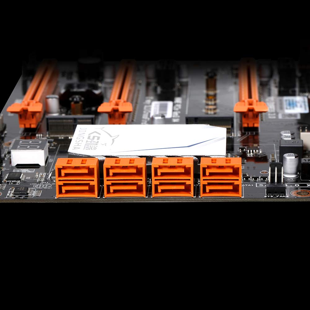
Abbildung 5.4: View of the eight orange SATA 3.0 ports on the motherboard, providing ample connectivity for storage devices.
5.4 Stromversorgung anschließen
- Connect the 24-pin ATX power connector from your power supply unit (PSU) to the corresponding port on the motherboard.
- Connect the 8-pin CPU power connector (EPS12V) from your PSU to the 8-pin port near the CPU socket.
5.5 Installing Expansion Cards (PCIe)
- Locate the desired PCI-E 3.0 x16 or x1 slots.
- Entfernen Sie die entsprechende Erweiterungssteckplatzabdeckung von Ihrem PC-Gehäuse.
- Align the expansion card with the slot and press down firmly until it is fully seated. Secure the card with a screw to the case.

Abbildung 5.5: Schräg view of the motherboard, highlighting the three PCI Express 3.0 x16 slots and the smaller PCIe x1 slots, ready for graphics cards and other expansion cards.
6. Bedienung des Motherboards
6.1 Erster Start und BIOS-Einrichtung
- Nachdem Sie alle Komponenten zusammengebaut haben, schließen Sie Monitor, Tastatur und Maus an.
- Power on your system. During the initial boot sequence, repeatedly press the DEL or F2 key (common for JINGSHA motherboards) to enter the BIOS/UEFI setup utility.
- Überprüfen Sie im BIOS, ob alle installierten Komponenten (CPU, RAM, Speicher) korrekt erkannt werden.
- Konfigurieren Sie die Bootreihenfolge, um Ihrem Betriebssystem-Installationsmedium (USB-Stick oder DVD) Priorität einzuräumen.
- Änderungen speichern und BIOS verlassen. Das System wird neu gestartet.
6.2 Installation des Betriebssystems
Follow the instructions provided with your operating system (e.g., Windows, Linux) to complete the installation process. Ensure you install all necessary drivers for the motherboard's chipsets, network, audio, and other components from the manufacturer's webWebsite oder mitgelieferte Treiber-CD.
7. Wartung
Durch sachgemäße Wartung wird die Langlebigkeit und der stabile Betrieb Ihres Motherboards sichergestellt.
- Staubentfernung: Reinigen Sie das Motherboard und die Komponenten regelmäßig mit Druckluft von Staub. Stellen Sie sicher, dass das System vor der Reinigung ausgeschaltet und vom Stromnetz getrennt ist.
- BIOS-Updates: Periodically check the Docooler or JINGSHA official website for BIOS updates. BIOS updates can improve compatibility, stability, and performance. Follow update instructions carefully to avoid damaging the motherboard.
- Treiber-Updates: Halten Sie Ihre Systemtreiber auf dem neuesten Stand, um optimale Leistung und Kompatibilität mit neuer Software und Hardware zu gewährleisten.
- Umgebungsbedingungen: Betreiben Sie das Motherboard in einer gut belüfteten Umgebung mit stabiler Temperatur und Luftfeuchtigkeit, um Überhitzung und Bauteilverschlechterung zu vermeiden.
8. Fehlerbehebung
In diesem Abschnitt werden häufig auftretende Probleme behandelt.
8.1 Kein Strom / Kein Startvorgang
- Ensure the 24-pin ATX and 8-pin CPU power connectors are securely plugged into the motherboard.
- Check if the power supply unit (PSU) is switched on and connected to a working power outlet.
- Verify that the front panel power button cable is correctly connected to the motherboard's header.
8.2 Keine Displayausgabe
- Ensure your graphics card (if dedicated) is properly seated in its PCI-E slot and has all necessary power cables connected.
- Check that your monitor cable is securely connected to the graphics card or motherboard (if integrated graphics are used, though X99 typically requires a dedicated GPU).
- Try reseating your RAM modules. Incorrectly seated RAM is a common cause of no display.
8.3 POST Code Display (Digital Diagnostic Card)
The motherboard is equipped with a digital diagnostic card (POST code display) that shows a two-digit code during boot-up. Refer to the motherboard's detailed technical documentation (often available on the manufacturer's website) for a list of POST codes and their meanings. This can help pinpoint the exact component causing a boot failure.

Abbildung 8.1: Nahaufnahme view showing the integrated digital diagnostic card (POST code display) on the motherboard, which assists in identifying hardware issues during boot.
9. Garantie und Support
For warranty information and technical support, please refer to the documentation provided with your purchase or visit the official Docooler or JINGSHA webBewahren Sie Ihren Kaufbeleg für Garantieansprüche auf.
Ask a question about this manual
Ask about setup, troubleshooting, compatibility, parts, safety, or missing instructions. Manuals+ will review the question and use this page’s manual context to help answer it.