
1. Einleitung
This manual provides detailed instructions for the Kadimendium ND0412SA DC-DC Step-up Module. This module is designed to convert a lower DC input voltage (2.6V-5.5V) into a higher, stable DC output voltage (selectable 5V, 6V, 9V, or 12V). It is suitable for various applications requiring a boosted power supply, such as battery-powered equipment, LED motors, and low-power electronic devices.
2. Sicherheitshinweise
- Ensure all power sources are disconnected before making any connections to the module.
- Observe correct polarity for input and output connections (Vi, GND, Vo). Incorrect polarity can damage the module and connected devices.
- Überschreiten Sie nicht die angegebene maximale Eingangslautstärketage or output current ratings.
- Avoid short circuits on the input or output terminals. While the module has short-circuit protection, prolonged short circuits can cause damage.
- Operate the module within its specified temperature range (-40°C to +85°C).
- Das Modul sollte vor Feuchtigkeit, Staub und korrosiven Umgebungen geschützt werden.
3. Produktüberschreitungview
The ND0412SA is a compact and efficient DC-DC boost converter. It features high efficiency (up to 93%) and incorporates multiple protection mechanisms including over current (OCP), over voltage (OVP), short circuit (SCP), and over temperature (OTP) to ensure reliable operation and extend the lifespan of the power supply.

Abbildung 3.1: Oben view of the ND0412SA module, displaying its compact design and main components.
The module's input terminals are labeled Vi (Eingangslautstärketage) and GND (Ground). The output terminals are labeled Vo (Ausgabe Voltage) and GND. The bottom side of the module features solder pads for selecting the desired output voltage.
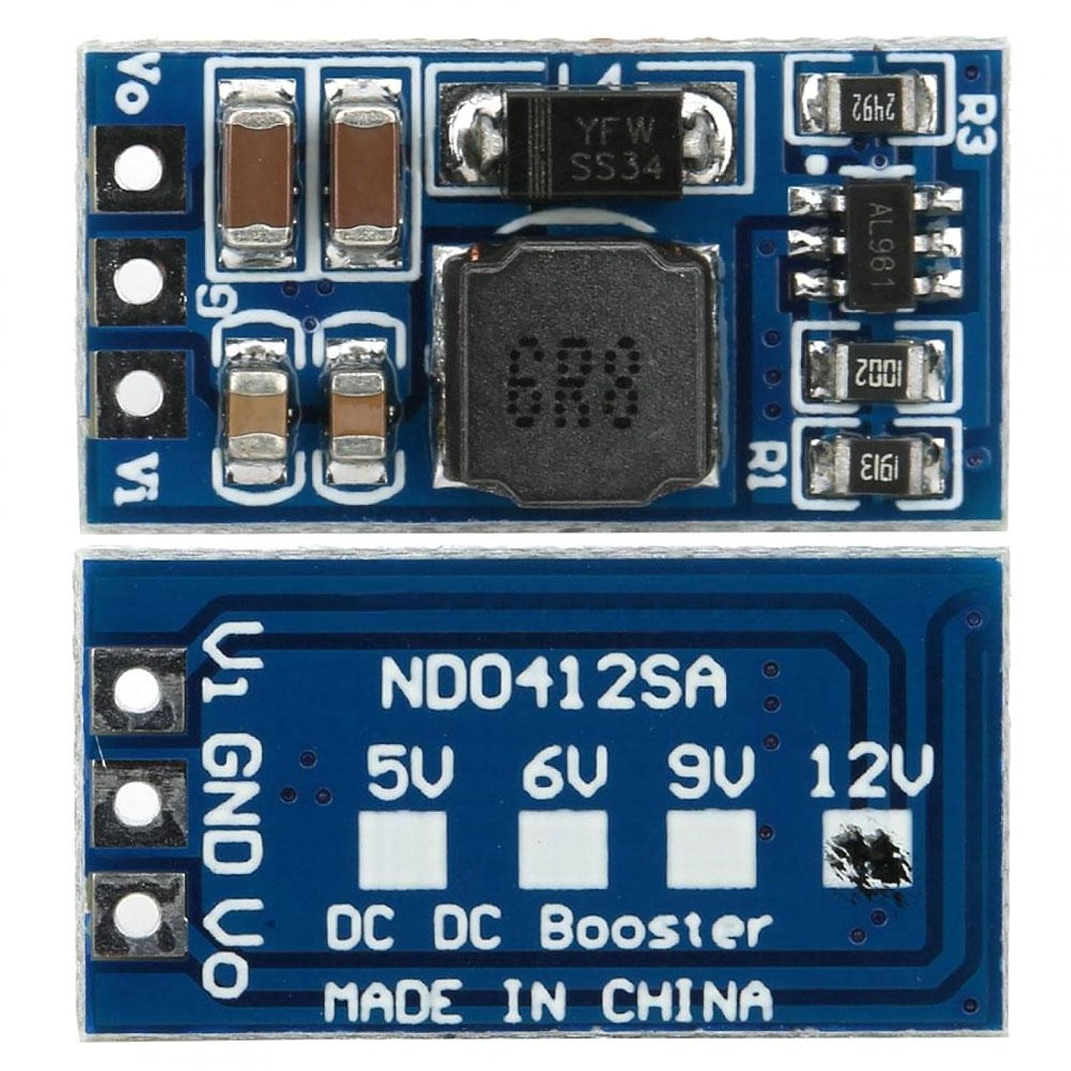
Abbildung 3.2: Unten view of the ND0412SA module, showing the output voltage selection pads.
4. Einrichtung
Follow these steps to set up your ND0412SA module:
- Ausgangsvolumentage Auswahl: Before connecting power, select your desired output voltage (5V, 6V, 9V, or 12V) by bridging the corresponding solder pads on the bottom of the module (refer to Figure 3.2). For example, to set the output to 12V, bridge the pad labeled '12V'. If no pads are bridged, the module may default to a specific voltage or operate unpredictably.
- Eingangsanschluss: Connect your DC input power source to the Vi and GND input terminals. Ensure the input voltage is within the 2.6V to 5.5V range.
- Ausgangsanschluss: Connect your load to the Vo and GND output terminals.
- Advanced Output Voltage and Current Limit Adjustment (Optional): For custom output voltages or current limits, the module allows adjustment via external resistors R1 and R3. This requires soldering and precise resistor values. Refer to Figure 4.1 for details.
- Ausgangsvolumentage (R1): The R1 resistor sets the output voltage. The formula is R1(KΩ) = 10 * (Vout / 0.6 - 1).
- Current Limit (R3): The R3 resistor programs the peak switch current. The resistor value should be between 10kΩ and 100kΩ. The current limit will be set from 2.5A to 0.5A. The formula is Iin = 48000 / R3.

Figure 4.1: Diagram for R1 (output voltage) and R3 (current limit) resistor settings.
5. Bedienungsanleitung
Once the module is correctly wired and the output voltage is selected, apply power to the input terminals. The module will automatically boost the input voltage to the selected output voltage. Überwachen Sie die Ausgangslautstärke.tage and current to ensure it meets your application's requirements and stays within the module's specifications.
6. Wartung
- Halten Sie das Modul sauber und frei von Staub und Schmutz.
- Ensure adequate ventilation, especially when operating at higher loads, to prevent overheating.
- Überprüfen Sie die Verbindungen regelmäßig auf Lockerung oder Korrosion.
- Avoid physical shock or excessive vibration to the module.
7. Fehlerbehebung
- Keine Ausgangsvoltage:
- Eingangslautstärke prüfentage, um sicherzustellen, dass die Spannung im Bereich von 2.6 V bis 5.5 V liegt.
- Verify input and output connections for correct polarity and secure contact.
- Stellen Sie sicher, dass die Ausgangslautstärketage selection pads are correctly bridged.
- Check for any short circuits on the output. The module's SCP may have activated.
- Falsche Ausgangslautstärketage:
- Re-verify the output voltage selection pads.
- If using custom R1 adjustment, double-check resistor value and soldering.
- Modulüberhitzung:
- Verringern Sie die an den Ausgang angeschlossene Last.
- Sorgen Sie für eine ausreichende Belüftung rund um das Modul.
- Prüfen Sie, ob die Eingangslautstärketage is too low, causing the module to draw excessive current.
- Intermittierender Betrieb:
- Check for loose connections or poor soldering.
- Ensure the module is not exposed to excessive electromagnetic interference.
8. Spezifikationen
| Parameter | Wert |
|---|---|
| Modell | ND0412SA |
| Eingangslautstärketage Reichweite | DC 2.6V ~ 5.5V |
| Ausgangsvolumentage Optionen | DC 5V, 6V, 9V, 12V (selectable) |
| Maximale Ausgangsleistung | 7W |
| Effizienz | Bis zu 93% |
| Betriebsfrequenz | 1 MHz |
| Abmessungen (ca.) | 21 x 11 x 4mm / 0.8 x 0.4 x 0.2in (without pin) |
| Betriebstemperatur | -40°C ~ +85°C |
| Schutzfunktionen | Over Current (OCP), Over Voltage (OVP), Short Circuit (SCP), Over Temperature (OTP) |
Typical Output Current (Reference Only):
| Ausgangsvolumentage | Eingangslautstärketage Reichweite | Max Ausgangsstrom |
|---|---|---|
| 5V | DC 2.6 ~ 4.5V | 1300 mA |
| 6V | DC 2.6 ~ 5.5V | 1200 mA |
| 9V | DC 2.6 ~ 5.5V | 800 mA |
| 12 V | DC 2.6 ~ 5.5V | 600 mA |
9. Garantie und Support
For warranty information or technical support, please refer to the product's purchase documentation or contact the retailer. Keep your proof of purchase for any warranty claims.