
PowMr ML2440
PowMr 40A MPPT Solarladeregler Benutzerhandbuch
Modell: ML2440
1. Einleitung
This manual provides essential information for the safe and efficient operation of your PowMr 40A MPPT Solar Charge Controller, model ML2440. Please read this manual thoroughly before installation and use to ensure optimal performance and longevity of the product.
2. Sicherheitshinweise
- Stellen Sie sicher, dass alle Kabel korrekt angeschlossen und befestigt sind, um Kurzschlüsse oder Beschädigungen zu vermeiden.
- Always connect the battery to the charge controller first, then the solar panels, and finally the load. Disconnect in the reverse order.
- Versuchen Sie nicht, den Controller selbst zu reparieren oder zu modifizieren. Wenden Sie sich zur Wartung an qualifiziertes Fachpersonal.
- Installieren Sie den Controller in einem gut belüfteten Bereich, fern von brennbaren Materialien und direkter Sonneneinstrahlung.
- Tragen Sie beim Arbeiten an elektrischen Anlagen geeignete persönliche Schutzausrüstung (PSA).
- Stellen Sie sicher, dass die Systemlautstärketage matches the controller's specifications (12V/24V auto-detection).
3. Produktüberschreitungview
The PowMr 40A MPPT Solar Charge Controller is designed to efficiently manage power from your solar panels to charge various battery types, including Lithium, Sealed, Gel, and Flooded batteries. It features Maximum Power Point Tracking (MPPT) technology for optimized solar energy harvesting, automatic 12V/24V system voltage detection, and a clear LCD display for monitoring system status.
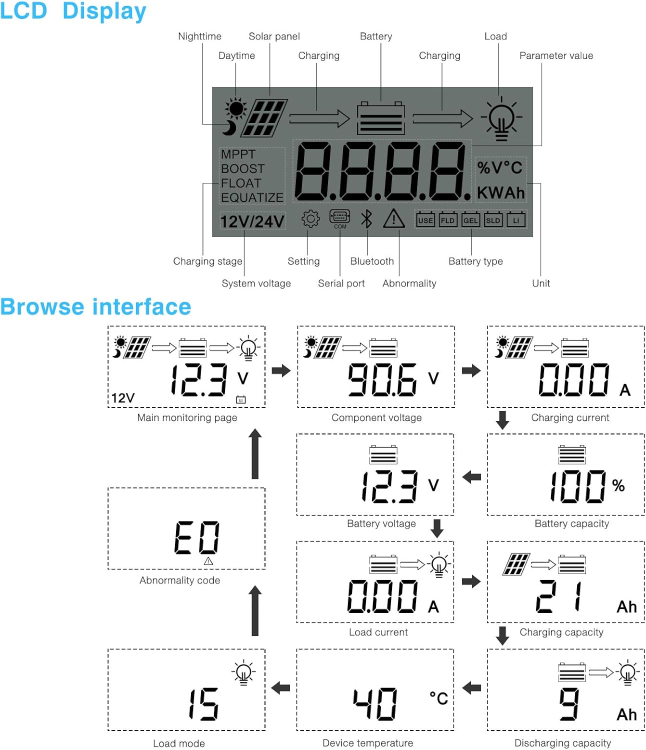
Abbildung 3.1: Front view des PowMr 40A MPPT Solar-Ladereglers.
This image shows the main unit of the PowMr 40A MPPT Solar Charge Controller, highlighting its compact design and integrated LCD screen.
The controller supports a maximum solar input voltage of 100V and a maximum input power of 1100W for a 24V system (550W for 12V). It also includes temperature compensation for accurate charging across varying environmental conditions.

Abbildung 3.2: Temperature compensation feature.
This image illustrates the temperature compensation capability of the controller, ensuring optimal battery charging performance in both hot and cold environments.
4. Installation und Verkabelung
Eine korrekte Installation ist entscheidend für den sicheren und effizienten Betrieb Ihres Solarladereglers. Befolgen Sie diese Schritte sorgfältig.
4.1 Schaltplan

Abbildung 4.1: Wiring diagram for the PowMr MPPT Solar Charge Controller.
This diagram illustrates the correct connection order for the battery, solar panels, DC load, and optional inverter. A temperature sensor is also shown.
4.2 Verbindungsschritte
- Zuerst die Batterie anschließen: Connect the battery to the charge controller's battery terminals. Ensure correct polarity. The controller will auto-detect 12V or 24V system voltage.
- Solarpaneele anschließen: Connect the solar panels to the PV input terminals. Ensure correct polarity. The controller will begin charging if sufficient sunlight is available.
- Gleichstromlast anschließen (optional): Wenn Sie eine Gleichstromlast direkt vom Controller verwenden, schließen Sie diese an die Lastklemmen an.
- Wechselrichter anschließen (optional): If using an inverter, connect it to the battery terminals (not directly to the load terminals of the controller).
- Temperatursensor anschließen: For accurate temperature compensation, connect the provided temperature sensor to the designated port on the controller and place the sensor near the battery.
Disconnection Order: To disconnect the system, always follow the reverse order: Disconnect load, then solar panels, then battery.
5. Bedienungsanleitung
This section details how to monitor and configure your charge controller using its integrated LCD display and the optional Bluetooth mobile application.
5.1 LCD-Anzeige überview

Abbildung 5.1: LCD Display and Browse Interface.
This image shows the various icons and parameters displayed on the LCD screen, along with the navigation flow through different monitoring pages.
The LCD provides real-time information about your solar system. Key indicators include:
- Aufladen Stage: MPPT, Boost, Float, Equalize.
- Systemlautstärketage: 12V/24V auto-detected.
- Akku-Typ: Icons for Lithium (Li), Sealed (SLD), Gel (GEL), Flooded (FLD).
- Statusanzeigen: Solar panel activity, battery charging, load status, abnormality.
- Parameterwert: Zeigt voltage, current, capacity, temperature, etc.
Use the buttons below the LCD to navigate through different screens to view parameters such as main monitoring page, component voltage, Ladestrom, Batteriespannungtage, battery capacity, load current, charging capacity, device temperature, discharging capacity, abnormality codes, and load mode.
5.2 Bluetooth Mobile Application
The controller supports an optional Bluetooth module (BT-1) for remote monitoring and parameter adjustment via a mobile application (available for Apple iOS and Android devices). The Bluetooth module connects to the RS232 port on the controller.

Abbildung 5.2: Controller with optional Bluetooth module.
This image displays the PowMr MPPT Solar Charge Controller alongside its optional BT-1 Bluetooth communication module and connecting cable.

Abbildung 5.3: BT-1 Bluetooth module.
Eine detaillierte view of the BT-1 Bluetooth module, which enables wireless communication with the solar charge controller for remote monitoring and settings adjustments.

Abbildung 5.4: Bluetooth Mobile Interface Display.
This image shows various screens from the mobile application, including real-time monitoring, data records, energy records, and parameter settings.
Die mobile Anwendung ermöglicht Ihnen Folgendes:
- Monitor real-time system data (voltage, current, power, temperature).
- View historical data and energy records.
- Adjust various charging parameters and battery settings.
- Wiederherstellen der Werkseinstellungen.
6. Wartung
Regular maintenance ensures the longevity and optimal performance of your charge controller.
- Reinigung: Reinigen Sie die Außenseite des Controllers regelmäßig mit einem trockenen Tuch, um Staub und Schmutz zu entfernen. Stellen Sie sicher, dass die Lüftungsöffnungen frei sind.
- Verbindungen: Überprüfen Sie jährlich alle Kabelverbindungen auf festen Sitz und Korrosion. Lose Verbindungen können zu Überhitzung und Leistungseinbußen führen.
- Umfeld: Ensure the installation environment remains within the specified operating temperature range and is free from excessive moisture or dust.
7. Fehlerbehebung
This section provides guidance for common issues. Refer to the LCD display for abnormality codes.
- Kein Display/Keine Stromversorgung:
- Überprüfen Sie die Batterieanschlüsse und stellen Sie sicher, dass die Batteriespannung ausreichend ist.tage liegt im Betriebsbereich.
- Verify that the battery fuse (if installed) is intact.
- Kein Aufladen:
- Stellen Sie sicher, dass die Solarpaneele korrekt angeschlossen sind und ausreichend Sonnenlicht erhalten.
- Überprüfen Sie die Lautstärke des Solarmodulstage und aktuell.
- Verify that the battery is not fully charged or in a protection state.
- Laden funktioniert nicht:
- Check load connections and ensure the load current does not exceed the controller's rating.
- Stellen Sie sicher, dass die Batterie voltage liegt über dem niedrigen Voltage Trennen (LVD) Einstellung.
- Check for any abnormality codes on the LCD related to load output.
- Abnormality Codes (e.g., "E0"):
- Refer to the specific abnormality code displayed on the LCD. Consult the full product manual or manufacturer's support for detailed explanations and solutions for each code.
8. Spezifikationen
Technical specifications for the PowMr 40A MPPT Solar Charge Controller (Model ML2440).

Abbildung 8.1: Product Specifications Table.
This table provides detailed technical parameters for the ML2420, ML2430, and ML2440 models. The ML2440 column is relevant for this 40A controller.
| Parameter | Value (ML2440) |
|---|---|
| Modell | ML2440 |
| Systemlautstärketage | 12V / 24V Auto |
| Leerlaufverlust | 0.7 W bis 1.2 W |
| Akku voltage | 9 bis 35 V |
| max. Solareingangsvolumentage | 100 V (25 °C), 90 V (-25 °C) |
| max. Steckdosenvolumentage Bereich | Akku voltage +2V bis 75V |
| Nennladestrom | 40 A |
| Nennlaststrom | 20 A |
| max. kapazitive Belastbarkeit | 10000uF |
| max. Eingangsleistung der Photovoltaikanlage | 550W/ 12V, 1100W/ 24V |
| Umwandlungseffizienz | ≤ 98 % |
| MPPT-Tracking-Effizienz | > 99 % |
| Temperaturkompensationsfaktor | -3.0mv/ °C/ 2V (default) |
| Betriebstemperatur | -35°C bis +45°C |
| Schutzart | IP32 |
| Gewicht | 2 kg |
| Kommunikationsmethode | RS232 |
| Höhe | ≤ 3000m |
| Produktabmessungen | 238*173*72.5 mm |
9. Garantie und Support
For warranty information, please refer to the documentation included with your product packaging or visit the official PowMr website. If you encounter any issues not covered in this manual or require further assistance, please contact PowMr customer support.
PowMr Official WebWebsite: Besuchen Sie den PowMr Store auf Amazon
Ask a question about this manual
Ask about setup, troubleshooting, compatibility, parts, safety, or missing instructions. Manuals+ will review the question and use this page’s manual context to help answer it.