1. Einleitung
This manual provides essential instructions for the safe and effective operation of your Generic DSO4102S Digital Storage Oscilloscope with an integrated Signal Generator. The DSO4102S is a versatile 2-channel instrument designed for various applications in electronics, including testing, measurement, and analysis. Please read this manual thoroughly before using the device to ensure proper functionality and to prevent damage.
2. Sicherheitshinweise
Always observe the following safety precautions to prevent injury and avoid damage to the instrument or other devices connected to it.
- Energiequelle: Connect the instrument only to a power source that meets the specifications listed in this manual.
- Erdung: Ensure the instrument is properly grounded to prevent electric shock. Do not defeat the grounding feature of the power cord.
- Umgebungsbedingungen: Operate the instrument in a dry environment, away from moisture, dust, and extreme temperatures.
- Belüftung: Ensure adequate ventilation around the instrument to prevent overheating. Do not block ventilation openings.
- Probes and Accessories: Use only probes and accessories supplied or recommended by the manufacturer. Ensure probes are rated for the voltage und Stromstärke werden gemessen.
- Wartung: Führen Sie keine Reparaturen am Instrument selbst durch. Überlassen Sie alle Reparaturen qualifiziertem Fachpersonal.
- Inspektion: Before each use, inspect the instrument, power cord, and accessories for any signs of damage. Do not use if damaged.
3. Produktüberschreitungview
3.1 Hauptmerkmale
- Designed with built-in digital control technology.
- Integrates the functions of a Digital Storage Oscilloscope and a Signal Generator.
- Suitable for a wide range of applications including manufacturing, research, testing, education, and electronic product repair.
- 2-channel input for simultaneous signal analysis.
- Hoch sampling rate of 1 GS/s for detailed waveform capture.
- Bandwidth of 100 MHz (for DSO4102S model).
3.2 Instrumentenkomponenten
The following images illustrate the main components and accessories of the DSO4102S oscilloscope.
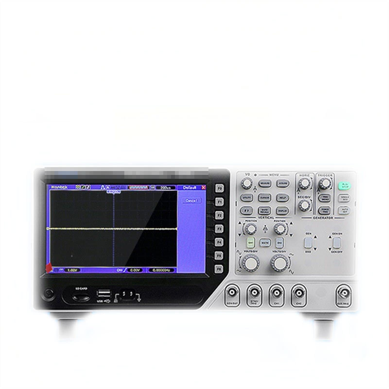
Abbildung 1: Front view of the DSO4102S Digital Storage Oscilloscope. This image shows the main display screen, control knobs for vertical and horizontal adjustments, trigger controls, and input BNC connectors for channels 1 and 2, along with the signal generator output.

Abbildung 2: Abgewinkelt view of the DSO4102S, highlighting the side profile and the arrangement of the front panel controls and connectors.

Abbildung 3: Oben und hinten view of the DSO4102S, showing ventilation slots and the power input port. The rear panel typically includes additional connectivity options such as USB for data transfer.

Abbildung 4: Included accessories for the DSO4102S, which typically comprise oscilloscope probes, a USB cable for PC connection, a power cord, and a BNC cable for signal generator output or other connections.
4. Einrichtung
- Auspacken: Carefully remove the oscilloscope and all accessories from the packaging. Verify that all components listed in Section 3.2 are present and undamaged.
- Stromanschluss: Connect the provided power cord to the power input port on the rear panel of the oscilloscope and then to a suitable AC power outlet. Ensure the power outlet is properly grounded.
- Einschalten: Press the power button, usually located on the front or side panel, to turn on the oscilloscope. The display should illuminate, and the system will perform a self-test.
- Sondenanschluss: For signal measurement, connect the oscilloscope probes to the CH1 and/or CH2 BNC input connectors on the front panel. Ensure the probe's ground clip is securely connected to the circuit's ground.
- Sondenkompensation: Before taking measurements, it is recommended to compensate the probes to ensure accurate readings. Connect the probe tip to the probe compensation test point (usually a square wave output) on the oscilloscope and adjust the probe compensation trimmer until a flat-top square wave is displayed.
5. Bedienungsanleitung
This section provides general guidance on operating the DSO4102S. Refer to the on-screen menus and specific function buttons for detailed control.
5.1 Oszilloskopfunktionen
- Vertical Controls (VOLTS/DIV): Use the VOLTS/DIV knobs for each channel to adjust the vertical scale (voltage per division) of the displayed waveform. The POSITION knob adjusts the vertical position.
- Horizontal Controls (SEC/DIV): Use the SEC/DIV knob to adjust the horizontal scale (time per division) of the displayed waveform. The HORIZ POSITION knob adjusts the horizontal position.
- Auslösesystem: The trigger controls (LEVEL, MODE, TYPE) stabilize repetitive waveforms. Adjust the TRIGGER LEVEL to set the voltage point at which the oscilloscope starts acquiring data. Select the appropriate trigger MODE (e.g., Auto, Normal, Single) and TYPE (e.g., Edge, Pulse).
- Messfunktionen: Most digital oscilloscopes include automatic measurement functions (e.g., Vpp, Vrms, Frequency, Period). Access these through the menu system to quickly analyze waveform parameters.
- Speicherung und Abruf: Use the instrument's storage functions to save waveforms, setups, or screenshots to internal memory or a connected USB drive.
5.2 Funktionen des Signalgenerators
The integrated signal generator allows you to output various waveforms for testing circuits.
- Ausgangsanschluss: Connect a BNC cable from the signal generator output port (labeled "GENERATOR" or similar) to the circuit under test.
- Wellenformauswahl: Use the dedicated signal generator controls or menu options to select the desired waveform type (e.g., sine, square, triangle, pulse).
- Frequenz und AmpHöhenanpassung: Stellen Sie die Frequenz ein und amplitude of the output signal using the corresponding controls or menu settings.
- Ausgabe aktivieren/deaktivieren: Use the ON/OFF button for the generator to enable or disable the signal output.
6. Wartung
- Reinigung: Vor der Reinigung das Netzkabel abziehen. Verwenden Sie ein weiches, fusselfreies Tuch.amp cloth with a mild detergent to clean the exterior of the instrument. Do not use abrasive cleaners or solvents. Avoid getting moisture into any openings.
- Lagerung: When not in use, store the oscilloscope in a clean, dry environment, away from direct sunlight and extreme temperatures. Protect it from dust and vibrations.
- Kalibrierung: For optimal performance and accuracy, periodic calibration by qualified service personnel is recommended. Refer to the manufacturer's guidelines for calibration intervals.
- Firmware-Updates: Überprüfen Sie die Angaben des Herstellers webBesuchen Sie die Website regelmäßig, um sicherzustellen, dass Ihr Gerät über die neuesten Funktionen und Fehlerbehebungen verfügt.
7. Fehlerbehebung
Dieser Abschnitt behandelt häufig auftretende Probleme. Bei Problemen, die hier nicht aufgeführt sind, wenden Sie sich bitte an den Kundendienst.
| Problem | Mögliche Ursache | Lösung |
|---|---|---|
| Kein Strom beim Einschalten. | Power cord not connected; power outlet faulty; instrument fuse blown. | Check power cord connection; test power outlet; contact service for fuse replacement. |
| Es wird keine Wellenform angezeigt. | Probe not connected; input signal too small/large; trigger settings incorrect; channel disabled. | Ensure probe is connected and making contact; adjust VOLTS/DIV; adjust trigger level/mode; enable channel. |
| Die Wellenform ist instabil oder rollend. | Incorrect trigger settings (level, mode, type). | Adjust trigger level to a stable point on the waveform; select appropriate trigger mode (e.g., Normal for stable signals); ensure trigger source is correct. |
| Falsche Messungen. | Probe compensation incorrect; probe attenuation setting incorrect; instrument not calibrated. | Perform probe compensation; ensure probe attenuation (e.g., 1X, 10X) matches oscilloscope setting; consider professional calibration. |
8. Spezifikationen
| Parameter | Wert |
|---|---|
| Modell | DSO4102S (100M) |
| Typ | Digitales Speicheroszilloskop |
| Anzahl der Kanäle | 2 |
| Bandbreite | 100 MHz (for DSO4102S) |
| Sampling-Rate | 1 GS/s |
| Artikelgewicht | 4 kg (4500 Gramm) |
| ASIN | B09KCBDQRL |
| Erstes verfügbares Datum | 26. Oktober 2021 |
Note: Specifications are subject to change without notice. For the most current specifications, please refer to the manufacturer's official documentation.
9. Garantie und Support
For warranty information, please refer to the documentation provided at the time of purchase or contact your seller directly. The manufacturer typically offers a limited warranty against defects in materials and workmanship.
If you encounter any issues or have questions regarding the operation or maintenance of your DSO4102S, please contact the seller or manufacturer's customer support. When contacting support, please have your model number (DSO4102S) and purchase details readily available.


