
1. Einleitung
The JZK F5305S Electronic Switch Control Board is a versatile MOSFET module designed for controlling high-power DC equipment. It features an optocoupler for complete isolation between input and output, ensuring stable and safe operation. This module is suitable for various applications, including controlling motors, light bulbs, LED strips, micro water pumps, and solenoid valves.
2. Produktüberschreitungview
The F5305S module acts as a pulse trigger switch, allowing digital high and low-level signals to control higher voltage and current loads. Its compact design integrates an F5305S power field effect tube, enabling efficient power switching and PWM control capabilities.
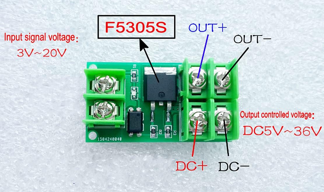
Figure 1: JZK F5305S Electronic Switch Control Board showing input and output terminals. Input signal voltage range is 3V-20V, and output controlled voltagDer Bereich liegt zwischen 5 und 36 V Gleichstrom.

Abbildung 2: Rückseite view of the JZK F5305S module, showing solder points and general layout.
3. Funktionen
- Signal Trigger Terminal: Accepts digital high and low-level signals (3V-24V input voltage, approximately 5mA current).
- Wide Output Control: Controls devices with 5V-36V DC voltage.
- Hohe Strombelastbarkeit: Handles currents up to 5A without a heatsink. For currents exceeding 5A (up to a maximum of 20A), an external heatsink is required.
- Vielseitige Anwendungen: Suitable for controlling high-power equipment such as motors, light bulbs, LED strips, DC motors, micro water pumps, and solenoid valves.
- PWM-Steuerung: Utilizes the original F5305S power field effect tube, allowing for Pulse Width Modulation (PWM) input to control motor speed or lamp Helligkeit.
- Opto-Isolation: Input and output terminals are completely isolated, enhancing safety and preventing interference.
4. Aufbau und Verkabelung
Proper wiring is crucial for the safe and effective operation of the F5305S module. Refer to Figure 1 for terminal identification.
- Input Signal Connection:
- Connect your control signal source (e.g., microcontroller IO port, PLC interface, DC power supply) to the Gleichstrom+ Und DC- terminals on the input side.
- Ensure the input signal voltage is within the 3V to 24V range.
- Ausgangslastanschluss:
- Connect the positive terminal of your DC load (e.g., motor, LED strip) to the AUS+ Terminal.
- Connect the negative terminal of your DC load to the AUS- Terminal.
- The output controlled voltage sollte zwischen 5V und 36V liegen.
- Power Supply for Load: The power supply for the load should be connected directly to the load, with the module acting as a switch in the load's circuit. The module switches the negative side of the load (low-side switching).
- Heatsink Requirement: If your load current exceeds 5A, you must attach an appropriate heatsink to the F5305S MOSFET to prevent overheating. The maximum current without a heatsink is 5A; with a heatsink, it can handle up to 20A.
5. Bedienungsanleitung
Once wired correctly, the F5305S module operates by receiving a trigger signal from your control source.
- Basic Switching: When a high-level signal (e.g., 3V-24V) is applied to the input terminals (DC+ and DC-), the MOSFET will turn on, allowing current to flow through the connected load. When the signal is removed or a low-level signal is applied, the MOSFET will turn off, cutting power to the load.
- PWM-Steuerung: For applications requiring variable control (e.g., motor speed, LED brightness), apply a Pulse Width Modulation (PWM) signal to the input terminals. The duty cycle of the PWM signal will directly control the average power delivered to the load.
- Anzeige-LED: The module typically includes a small LED to indicate the status of the switch (on/off).
6. Wartung
The JZK F5305S module is designed for reliable operation with minimal maintenance. Follow these guidelines:
- Sauber halten: Ensure the module is free from dust, dirt, and moisture. Use a soft, dry brush or compressed air for cleaning if necessary.
- Verbindungen prüfen: Überprüfen Sie regelmäßig alle Kabelverbindungen, um sicherzustellen, dass sie sicher und korrosionsfrei sind.
- Wärmemanagement: If operating at high currents (above 5A), regularly check the heatsink (if installed) for proper attachment and ensure adequate airflow around the module to prevent overheating.
- Vermeiden Sie körperlichen Stress: Do not apply excessive force or bend the circuit board, as this can damage components or solder joints.
7. Fehlerbehebung
If you encounter issues with your F5305S module, consider the following troubleshooting steps:
- Module Not Switching:
- Verify that the input signal voltage liegt im Bereich von 3 V – 24 V.
- Check if the input signal current is sufficient (around 5mA).
- Ensure all input and output connections are correct and secure.
- Test the input signal source independently to confirm it is functioning.
- Load Not Receiving Full Power/Dim Output:
- Confirm the output controlled voltage liegt im Bereich von 5 V – 36 V.
- Check the load's power requirements and ensure the module's current capacity (with or without heatsink) is not exceeded.
- If using PWM, verify the duty cycle and frequency of the PWM signal.
- Modulüberhitzung:
- Reduce the load current if it exceeds 5A without a heatsink.
- Install an appropriate heatsink if the current is between 5A and 20A.
- Sorgen Sie für ausreichende Belüftung rund um das Modul.
- No Indicator LED Activity: This may indicate no input signal, incorrect input wiring, or a faulty module. Recheck input connections and signal source.
8. Spezifikationen
| Parameter | Wert |
|---|---|
| Modellnummer | M467862U |
| Eingangssignal Voltage | 3 V – 24 V Gleichstrom |
| Eingangssignalstrom | Ungefähr 5 mA |
| Output Controlled Voltage | 5 V – 36 V Gleichstrom |
| Output Current (No Heatsink) | Weniger als 5A |
| Output Current (With Heatsink) | Up to 20A (Maximum) |
| Isolationsart | Optocoupler (Input and Output Isolated) |
| Abmessungen (ca.) | 47 mm x 25 mm x 15 mm (Länge x Breite x Höhe) |
| Artikelgewicht | Approximately 1.76 ounces (per module) |

Figure 3: Approximate dimensions of the JZK F5305S module.
9. Sicherheitshinweise
Please read and follow these safety precautions to prevent injury or damage to the module and connected equipment:
- Always disconnect power before making any connections or disconnections to the module.
- Ensure all wiring is correct and secure to prevent short circuits or improper operation.
- Do not exceed the maximum input signal voltage (24V) or output controlled voltage (36 V).
- Do not exceed the maximum output current (20A with heatsink, 5A without heatsink). Overcurrent can cause permanent damage to the module and pose a fire hazard.
- Operate the module in a dry environment, away from moisture, dust, and corrosive substances.
- Bewahren Sie das Modul außerhalb der Reichweite von Kindern auf.
- If the module shows signs of damage or malfunction, discontinue use immediately.
10. Packungsinhalt
Each package typically contains:
- 4 x JZK F5305S Electronic Switch Control Board Modules

Figure 4: Four JZK F5305S Electronic Switch Control Boards as typically included in a package.

Abbildung 5: Bspample of product packaging for the JZK F5305S modules.
11. Garantie und Support
Informationen zur Garantie oder technische Unterstützung finden Sie in den Richtlinien des Verkäufers oder wenden Sie sich direkt an den Hersteller. Bewahren Sie Ihren Kaufbeleg für eventuelle Garantieansprüche auf.