
1. Einleitung
This manual provides detailed instructions for the installation, operation, and maintenance of your BooiParts G31T-LM V1.0 Desktop Motherboard. Please read this manual thoroughly before proceeding with installation to ensure proper setup and to prevent damage to the components.
2. Sicherheitshinweise
- Vor dem Einbau oder Ausbau von Bauteilen muss immer die Stromversorgung von der Steckdose getrennt werden.
- Wear an anti-static wrist strap or frequently touch a grounded metal object to discharge static electricity before handling the motherboard or other components. Static electricity can damage sensitive electronic parts.
- Fassen Sie das Motherboard an den Kanten an, um eine Berührung empfindlicher Bauteile zu vermeiden.
- Stellen Sie sicher, dass alle Kabel korrekt und sicher angeschlossen sind, bevor Sie das System einschalten.
- Das Motherboard darf weder Feuchtigkeit noch extremen Temperaturen ausgesetzt werden.
3. Packungsinhalt
Prüfen Sie, ob alle Artikel in Ihrem Paket enthalten sind. Sollten Artikel fehlen oder beschädigt sein, wenden Sie sich bitte an Ihren Händler.
- BooiParts G31T-LM V1.0 Desktop Motherboard
- I/O Shield (may be included)
- SATA Data Cable (may be included)
- Benutzerhandbuch (dieses Dokument)
4. Produktüberschreitungview
The BooiParts G31T-LM V1.0 motherboard is designed for Intel LGA 775 processors and supports DDR2 memory. Below are key components and their locations.
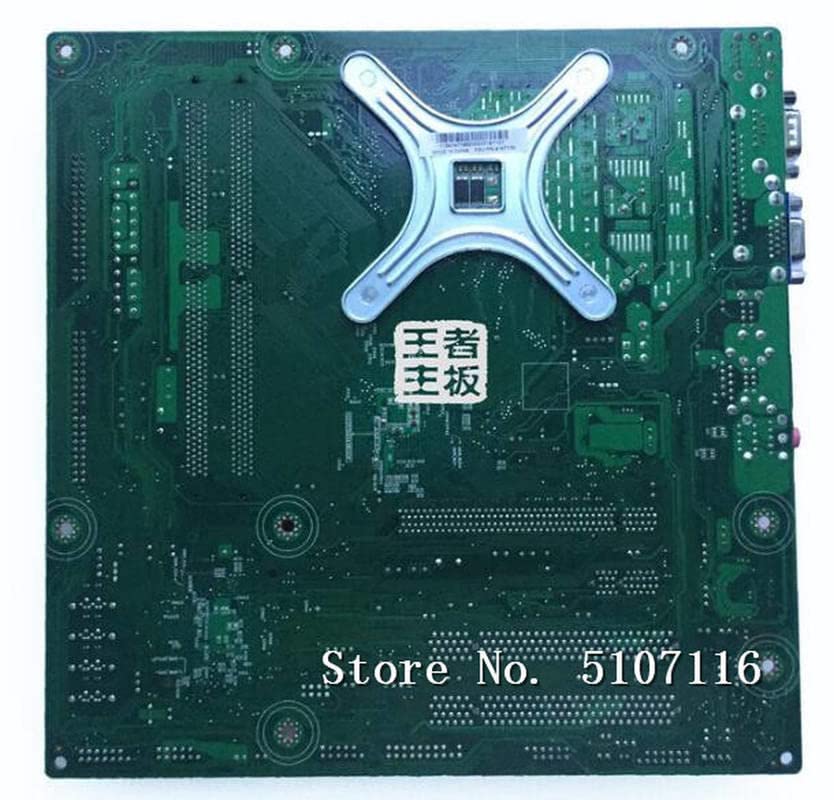
Abbildung 4.1: Spitze view of the BooiParts G31T-LM V1.0 motherboard. This image highlights the central LGA 775 CPU socket, two DDR2 RAM slots to its right, and various expansion slots (PCIe and PCI) below the CPU area. Power connectors and SATA ports are also visible along the edges.

Abbildung 4.2: Abgewinkelt view of the BooiParts G31T-LM V1.0 motherboard. This perspective provides a clearer view of the rear I/O panel, including PS/2 ports, serial port, VGA output, USB ports, Ethernet port, and audio jacks. Key components like the chipset heatsink and power delivery components are also visible.
4.1 Schlüsselkomponenten
- LGA 775 CPU-Sockel: For Intel Core 2 Duo and Pentium D processors.
- DDR2-DIMM-Steckplätze: Two slots supporting up to 8GB DDR2 memory.
- PCI-Express-Steckplatz: Für Grafikkarten.
- PCI-Steckplätze: Für weitere Erweiterungskarten.
- SATA-Anschluss: For connecting storage devices.
- Hinteres I/O-Panel: Includes PS/2 ports, USB ports, VGA, LAN, and audio jacks.
5. Einrichtung
5.1 Vorbereitung
- Ensure your computer case is compatible with Micro-ATX motherboards.
- Gather all necessary components: CPU, CPU cooler, DDR2 RAM, power supply, storage devices, and graphics card (if not using integrated graphics).
5.2 CPU-Installation
- Suchen Sie den LGA 775-Sockel auf dem Motherboard.
- Heben Sie den Lasthebel an und öffnen Sie die CPU-Sockelabdeckung.
- Carefully align the CPU with the socket, ensuring the notches on the CPU match the keys on the socket. Do not force the CPU into place.
- Schließen Sie die Steckdosenabdeckung und drücken Sie den Lasthebel nach unten, bis er einrastet.
5.3 Installation des CPU-Kühlers
Apply thermal paste to the CPU if not pre-applied on the cooler. Install the CPU cooler according to its manufacturer's instructions, ensuring it is securely fastened and the fan cable is connected to the CPU_FAN header on the motherboard.
5.4 RAM-Installation
- Öffnen Sie die Klemmen an beiden Enden der DDR2-DIMM-Steckplätze.
- Richten Sie das RAM-Modul am Steckplatz aus und achten Sie darauf, dass die Kerbe am Modul mit der entsprechenden Aussparung im Steckplatz übereinstimmt.
- Drücken Sie beide Enden des RAM-Moduls fest nach unten, bis die Klammern einrasten.
5.5 Einbau des Motherboards in das Gehäuse
- Installieren Sie die I/O-Blende in die hintere Öffnung Ihres Computergehäuses.
- Carefully place the motherboard into the case, aligning the screw holes on the motherboard with the standoffs in the case.
- Befestigen Sie das Motherboard mit Schrauben. Ziehen Sie die Schrauben nicht zu fest an.
5.6 Stromversorgung anschließen
- Verbinden Sie den 24-poligen ATX-Stromanschluss Ihres Netzteils mit dem entsprechenden Anschluss auf dem Motherboard.
- Connect the 4-pin ATX 12V power connector (CPU power) to its header near the CPU socket.
5.7 Anschließen von Speichergeräten
Connect your SATA storage devices (HDD/SSD) to the SATA port on the motherboard using a SATA data cable. Connect the power cable from your power supply to the storage device.
5.8 Connecting Front Panel Connectors
Connect the front panel cables (Power SW, Reset SW, HDD LED, Power LED, USB, Audio) from your case to the corresponding headers on the motherboard. Refer to the motherboard's silkscreen labels for correct pin orientation.
5.9 Anschließen von Peripheriegeräten
Schließen Sie Ihre Tastatur, Maus, Ihren Monitor und andere Peripheriegeräte an die entsprechenden Anschlüsse auf der Rückseite des I/O-Panels an.
6. Bedienungsanleitung
6.1 Erster Start
After completing all connections, turn on your power supply and press the power button on your computer case. The system should power on, and you should see a display on your monitor. If not, refer to the Troubleshooting section.
6.2 BIOS/UEFI-Einrichtung
Drücken Sie beim Startvorgang die angegebene Taste (normalerweise DEL or F2) to enter the BIOS/UEFI setup utility. Here you can configure system settings, boot order, and monitor hardware status.
7. Wartung
- Reinigung: Reinigen Sie das Motherboard und die Komponenten regelmäßig mit Druckluft von Staub. Stellen Sie sicher, dass das System vor der Reinigung ausgeschaltet und vom Stromnetz getrennt ist.
- BIOS-Updates: Überprüfen Sie die Angaben des Herstellers webWebsite für BIOS-Updates. Aktualisieren Sie das BIOS nur, wenn es unbedingt notwendig ist, und befolgen Sie die Anweisungen sorgfältig, um Systeminstabilität zu vermeiden.
- Kabelmanagement: Sorgen Sie für eine ordentliche Kabelführung, um die Luftzirkulation zu verbessern und Störungen zu vermeiden.
8. Fehlerbehebung
8.1 Kein Strom
- Check if the power supply is switched on and properly connected to the motherboard (24-pin and 4-pin connectors).
- Stellen Sie sicher, dass das Netzschalterkabel an der Vorderseite korrekt an den Anschluss auf dem Motherboard angeschlossen ist.
- Testen Sie das Netzteil mit einem anderen System oder einem Netzteilprüfgerät.
8.2 Keine Anzeige
- Verify that the monitor is connected to the correct video output (onboard VGA or discrete graphics card).
- Setzen Sie die RAM-Module neu ein. Falsch eingesetzter RAM ist eine häufige Ursache für einen fehlenden Bildschirm.
- If using a discrete graphics card, ensure it is properly seated in its PCIe slot and has adequate power connected.
- Versuchen Sie, mit nur einem RAM-Riegel zu starten.
8.3 Systeminstabilität/Abstürze
- Überprüfen Sie die Temperaturen von CPU und GPU. Überhitzung kann zu Instabilität führen.
- Stellen Sie sicher, dass alle Treiber auf dem neuesten Stand sind.
- Führen Sie Speicherdiagnosetools aus, um den Arbeitsspeicher auf Fehler zu überprüfen.
- Überprüfen Sie die Stromversorgung.tage ist für alle Komponenten ausreichend.
9. Spezifikationen
The following table outlines the key specifications for the BooiParts G31T-LM V1.0 Motherboard.
| Besonderheit | Spezifikation |
|---|---|
| Marke | BooiParts |
| Modellname | G31T-LM V1.0 |
| CPU-Sockel | LGA 775 |
| Kompatible Prozessoren | Intel Core 2 Duo, Intel Pentium D |
| Chipsatztyp | Intel G31 |
| RAM-Speichertechnologie | DDR2 |
| Verfügbare Speichersteckplätze | 2 |
| Speicherkapazität (Max.) | 8 GB |
| Grafikkartenschnittstelle | PCI Express |
| Total SATA Ports | 1 |
| Total PCIe Ports | 2 |
| Hauptstromanschlusstyp | 24-polig |
| Kompatible Geräte | Personalcomputer |
| Modellnummer | T4900V 53Y3282 45C2882 |
10. Garantie und Support
Informationen zur Garantie und zum technischen Support finden Sie in der mitgelieferten Dokumentation oder wenden Sie sich an Ihren Händler. Bewahren Sie Ihren Kaufbeleg für Garantieansprüche auf.