
1. Einleitung
This manual provides detailed instructions for the installation, operation, and maintenance of the QIACHIP Mini Wireless Remote Control Switch. This device is designed to provide wireless control for various DC applications, including LED lights, car batteries, and door locks, operating within a voltagDer Bereich von DC 6V bis 60V.

Figure 1: QIACHIP Mini Wireless Remote Control Switch (1 Receiver + 1 Transmitter)
2. Produktüberschreitungview
Hauptmerkmale:
- Breites Volumentage Reichweite: Eingangsvolumentage DC 5V-60V, supporting various DC applications.
- Hohe Strombelastbarkeit: Maximum relay contact current of 20 Amps.
- HF-Frequenz: Arbeitet auf 433 MHz für zuverlässige drahtlose Kommunikation.
- Erweiterte Übertragungsdistanz: Approximately 50-100m in open spaces. The antenna can be extended for improved reception.
- Mehrere Betriebsmodi: Unterstützt die Modi Momentary, Toggle, Latched und Delay.
- Kompatibilität der Fernbedienung: Supports EV1527 learning code remote controllers, allowing pairing with up to 20 remotes.
- Kompaktes Design: PCB size of 47 x 26 x 18 mm (L, W, H).
- Vielseitige Anwendungen: Suitable for car battery power control, garage doors, electronic doors, appliances, motorcycle alarms, car sunroofs, and heating systems.

Figure 2: Product application examples for lighting control.

Figure 3: Enhanced features of the remote switch, including an exposed antenna for better reception and a wider voltage Reichweite.
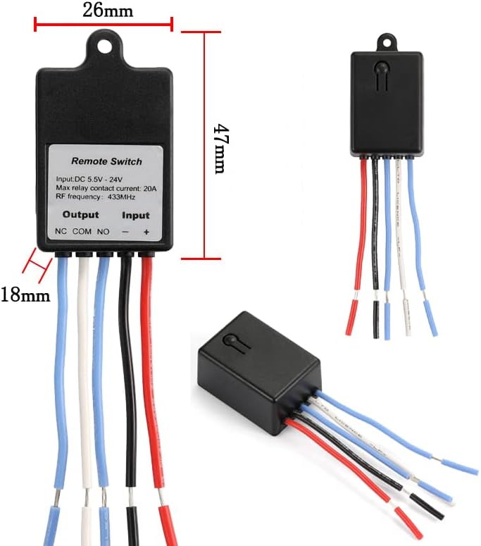
Figure 4: Physical dimensions of the remote control switch.

Figure 5: Internal components and terminal labels of the remote switch.
3. Spezifikationen
| Spezifikation | Wert |
|---|---|
| Betriebsmodus | EIN-AUS |
| Aktuelle Bewertung | 20 Amps |
| Betriebslautstärketage | Gleichstrom 5 V bis 60 V |
| Kontakttyp | Normally Open (NO), Normally Closed (NC), Common (COM) |
| Steckertyp | Kabellos |
| Terminal | Lot |
| Artikelabmessungen (L x B x H) | 1.85 x 1.02 x 0.71 Zoll (47 x 26 x 18 mm) |
| Schaltungsart | 1-Wege |
| Kontaktmaterial | Plastik |
| Internationale Schutzbewertung | IP54 |
| Anzahl Positionen | 2 |
| Kontrollmethode | Fernbedienung |
| Konnektivitätsprotokoll | 433 MHz |
| Wastage | 480 Watt |
| Artikelgewicht | 1.76 Unzen |
| Batterien (Sender) | 1 CR2032-Batterie erforderlich (im Lieferumfang enthalten) |
4. Installation und Verkabelung
The QIACHIP remote control switch features three output terminals: NC (normalerweise geschlossen), COM (Allgemein), Und NO (Normalerweise offen). These terminals function like a Single-Pole Double-Throw (SPDT) switch. The input terminals are labeled + Und - for DC power connection.
Wiring Principles:
- COM: This is the common terminal where the power source or load is typically connected.
- NC: Normally Closed. This terminal is connected to COM by default when the relay is inactive.
- NEIN: Normally Open. This terminal is disconnected from COM by default when the relay is inactive. It connects to COM when the relay is activated.
- Input Power (+ and -): Connect your DC power supply (5V-60V) to these terminals to power the receiver module.
Typische Schaltpläne:

Figure 6: Wiring for a DC load (e.g., LED light). The load is connected to NO and COM, and the receiver is powered by the DC source.

Figure 7: Wiring for an access control or door lock system. The lock is connected to NO and COM, and the receiver is powered by the DC source.

Figure 8: Wiring for an external power supply load. The remote switch controls the load's circuit via NO and COM, while the load has its own power source.
Wichtig: Stellen Sie stets sicher, dass die Spannung des Netzteilstage matches the requirements of your load and the remote switch. Incorrect wiring can damage the device or connected components.
5. Operating Modes and Pairing Instructions
The QIACHIP remote control switch supports four operating modes: Momentary, Toggle, Latched, and Delay. Each mode offers different control behaviors. To change modes, you must first perform a reset. After the reset, all previously paired remote controls are temporarily deactivated.
Video: Wiring and Pairing Demonstration
Video 1: This video demonstrates the wiring process and how to pair the remote control switch in different operating modes (Momentary, Toggle, Latched, and Delay Off).
5.1. Momentanmodus
In Momentary mode, the output is active only while the remote button is pressed. Releasing the button deactivates the output.
- Paarung: Drücken Sie die Lerntaste am Empfänger einmal. The indicator light will turn on. Then, press any button on your remote control. The indicator light will flash and turn off, indicating successful pairing.

Figure 9: Momentary Mode operation.
5.2. Toggle-Modus
In Toggle mode, pressing the remote button once activates the output, and pressing it again deactivates the output.
- Paarung: Drücken Sie die Lerntaste am Empfänger zweimal. The indicator light will turn on. Then, press any button on your remote control. The indicator light will flash and turn off, indicating successful pairing.

Figure 10: Toggle Mode operation.
5.3. Verriegelter Modus
In Latched mode, one remote button activates the output, and another remote button deactivates it. This mode requires a multi-button remote.
- Paarung: Drücken Sie die Lerntaste am Empfänger dreimal. The indicator light will turn on. Then, press the first button (e.g., 'A') on your remote, followed by the second button (e.g., 'B'). The indicator light will flash and turn off, indicating successful pairing.

Figure 11: Latched Mode operation.
5.4. Delay Off Mode
In Delay Off mode, the output activates when the remote button is pressed and remains active for a set duration (e.g., 5, 10, 15, or 20 seconds) before automatically deactivating.
- Pairing for 5-second delay: Drücken Sie die Lerntaste am Empfänger viermal. The indicator light will turn on. Then, press any button on your remote control. The indicator light will flash and turn off, indicating successful pairing.
- Pairing for 10-second delay: Drücken Sie die Lerntaste am Empfänger fünfmal.
- Pairing for 15-second delay: Drücken Sie die Lerntaste am Empfänger sechsmal.
- Pairing for 20-second delay: Drücken Sie die Lerntaste am Empfänger siebenmal.

Figure 12: Delay Off Mode operation.
5.5. Resetting All Paired Remotes
To clear all previously paired remote controls and reset the receiver to its default state, follow these steps:
- Drücken Sie die Lerntaste am Empfänger achtmal. The indicator light will flash rapidly and then turn off. This indicates that all stored remote control data has been erased.
6. Wartung
The QIACHIP Mini Wireless Remote Control Switch is designed for durability and requires minimal maintenance. Keep the device clean and free from dust and moisture. Ensure all wiring connections are secure to prevent intermittent operation. Replace the CR2032 battery in the transmitter when its range decreases or it stops responding.
7. Fehlerbehebung
- Gerät reagiert nicht auf Fernzugriff:
- Check if the remote control battery is depleted. Replace if necessary.
- Stellen Sie sicher, dass der Empfänger ordnungsgemäß mit Strom versorgt wird (DC 5V-60V).
- Verify that the remote is paired correctly to the receiver in the desired mode. If unsure, perform a reset and re-pair.
- Check for strong RF interference in the environment.
- Reduzierte Reichweite der Fernbedienung:
- Ersetzen Sie die Batterie der Fernbedienung.
- Ensure the receiver's antenna is not obstructed and is extended if possible.
- Minimize physical obstructions (walls, metal objects) between the remote and receiver.
- Output not activating/deactivating correctly:
- Verify wiring connections to NC, COM, and NO terminals are correct for your application.
- Ensure the load's power requirements do not exceed the relay's maximum contact current (20A) or wattage (480W).
- Confirm the operating mode is set as intended (Momentary, Toggle, Latched, Delay).
- Indicator light not functioning:
- Überprüfen Sie die Stromversorgung des Empfängers.
- If the device is otherwise functional, the indicator light may be faulty, but this does not affect core operation.
8. Garantie und Support
For warranty information or technical support, please refer to the product packaging or contact QIACHIP customer service through the retailer where the product was purchased. Keep your purchase receipt for warranty claims.