
DAOKAI WE-DA-144
DAOKAI Mini L298N DC Motor Driver Module Instruction Manual
Model: WE-DA-144
1. Einleitung
This manual provides detailed instructions for the DAOKAI Mini L298N DC Motor Driver Module. This compact module is designed to control DC motors and 4-wire two-phase stepper motors, offering features like speed regulation and direction control. It is suitable for various applications, including battery-powered smart cars, toy cars, and robotics projects.

Bild 1.1: Überview of the DAOKAI Mini L298N DC Motor Driver Modules and included Dupont cables.
2. Produktmerkmale
- Efficient Driver Chip: Utilizes a professional driver chip with built-in low on-resistance MOS switch, resulting in minimal heat generation and no need for an external heat sink.
- Dual H-Bridge Design: Capable of simultaneously driving two DC motors or one 4-wire two-phase stepper motor.
- Hohe Strombelastbarkeit: Each channel supports a continuous operating current of 1.5A, with a peak current capability of up to 2.5A.
- Überhitzungsschutz: Features an integrated overheating protection circuit (TSD) with hysteresis effect to prevent damage from motor stalls. The module automatically recovers once the temperature decreases.
- Anti-Common State Conduction: A built-in circuit prevents motor malfunction if input terminals are left floating.
- Geringer Stromverbrauch: Designed for low power consumption with a standby current of less than 0.1uA, making it ideal for battery-powered applications.
- Kompakte Größe: Small and lightweight design (24.7 x 21 x 5 mm) for easy integration into various projects.

Image 2.1: The motor driver module showcasing its compact size and key features like overheating protection and double H-bridge.
3. Packungsinhalt
Das Paket enthält die folgenden Artikel:
- 5 x Mini L298N DC Motor Driver Modules
- 1 x 40-Pin Header
- 1 x 40-Pin Female to Male Dupont Cable

Image 3.1: The retail packaging showing the included components.
4. Spezifikationen
| Parameter | Wert |
|---|---|
| Modulversorgungsvolumentage | 2 V - 10 V |
| Signaleingangsvoltage | 1.8 V - 7 V |
| Single Channel Operating Current | 1.5A (Dauerbetrieb) |
| Spitzenstrom | Bis zu 2.5A |
| Low Standby Current | Kleiner als 0.1uA |
| Produktabmessungen (L x B x H) | 24.7 x 21 x 5 mm (0.97 x 0.83 x 0.19 Zoll) |
| Artikelmodellnummer | WE-DA-144 |
| Aktuelle Bewertung | 1.5 Amps |
| Montagetyp | Unterputz |
| Anzahl der Pole | 2 |

Image 4.1: Visual representation of the module's key electrical parameters.
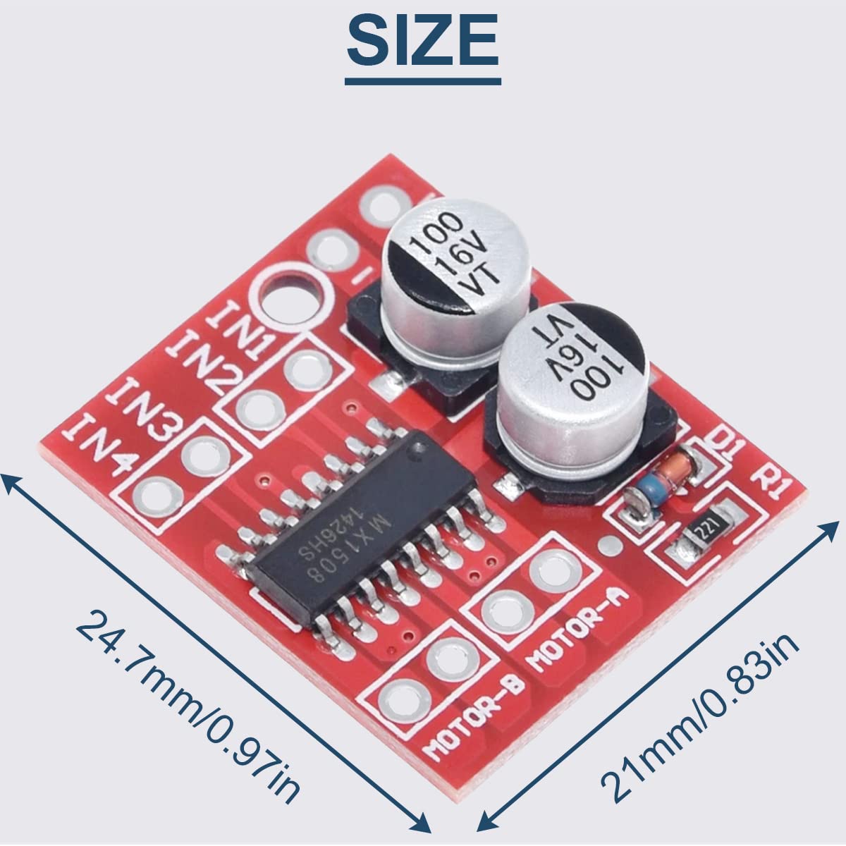
Image 4.2: Detailed dimensions of the motor driver module.
5. Einrichtung
Follow these steps to connect the DAOKAI Mini L298N DC Motor Driver Module:
- Stromversorgungsanschluss: Connect your DC power source (2V-10V) to the '+' and '-' terminals on the module. Ensure correct polarity.
- Motoranschlüsse: Connect your DC motors to the 'MOTOR-A' and 'MOTOR-B' output terminals. Each motor requires two connections.
- Steuersignaleingang: Connect your microcontroller (e.g., Arduino) to the IN1, IN2, IN3, and IN4 pins. These pins control the direction and speed of the motors.

Image 5.1: Wiring diagram illustrating power, motor, and control signal connections for the module.
6. Bedienungsanleitung
The module controls DC motors using the IN1, IN2 (for Motor-1) and IN3, IN4 (for Motor-B) input pins. The signal voltage range for these inputs is 1.8V-7V. Refer to the truth table below for control logic:
| Gleichstrommotoren | So drehen Sie | IN1 | IN2 | IN3 | IN4 |
|---|---|---|---|---|---|
| Motor-1 | Forward Rotation (Speed Regulation) | 1/PWM | 0 | ||
| Reverse (Flip) | 0 | 1/PWM | |||
| Standby-Modus | 0 | 0 | |||
| Bremsen | 1 | 1 | |||
| Motor-B | Forward Rotation (Speed Regulation) | 1/PWM | 0 | ||
| Reverse (Flip) | 0 | 1/PWM | |||
| Standby-Modus | 0 | 0 | |||
| Bremsen | 1 | 1 |
Notiz:
- "1" represents a high logic level.
- "0" represents a low logic level.
- "PWM" indicates Pulse Width Modulation, which can be used to adjust motor speed by varying the duty cycle.
- IN1 and IN2 control DC Motor A; IN3 and IN4 control DC Motor B. The two circuits operate independently.
- The input terminal INx has an anti-common state conduction function, meaning it acts as a low-level input when floating.
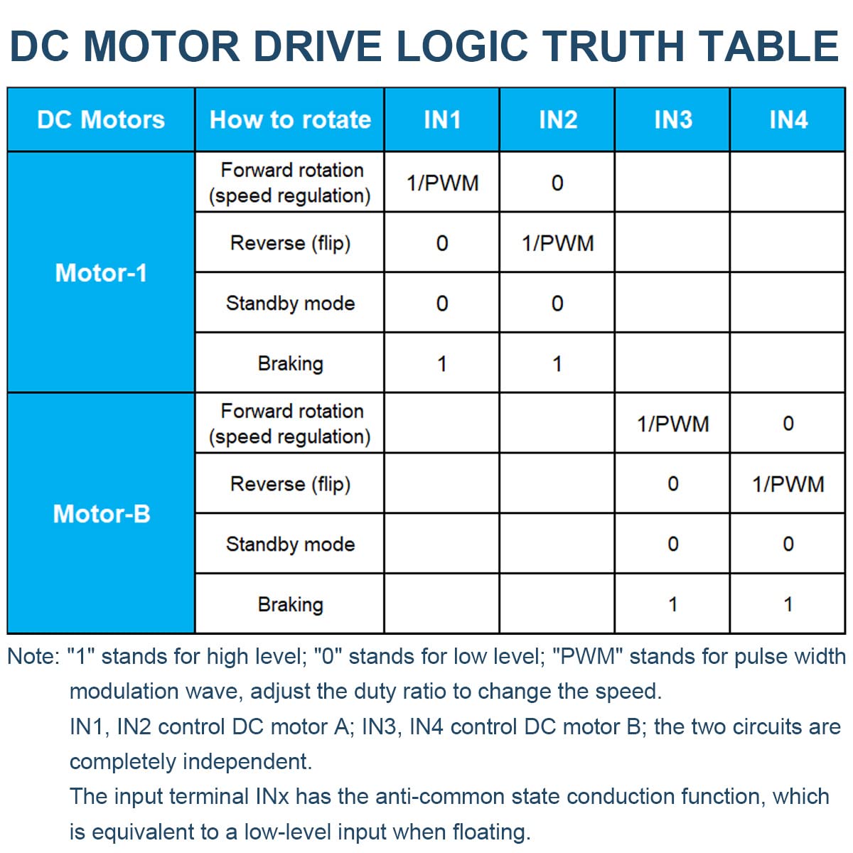
Image 6.1: Logic truth table detailing how to control motor direction and speed using the input pins.
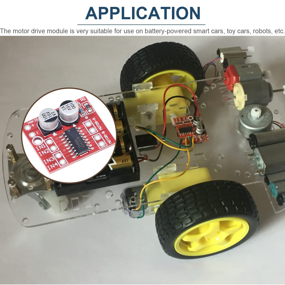
Abbildung 6.2: Beispielample application of the motor driver module integrated into a small robotic car.
7. Wartung
The DAOKAI Mini L298N DC Motor Driver Module is designed for durability and requires minimal maintenance. To ensure optimal performance and longevity:
- Sauber halten: Regularly inspect the module for dust or debris and gently clean with a soft, dry brush if necessary.
- Feuchtigkeit vermeiden: Protect the module from water and excessive humidity, which can cause short circuits and damage.
- Richtige Lagerung: When not in use, store the module in a dry, anti-static environment, away from extreme temperatures.
- Verbindungen prüfen: Überprüfen Sie regelmäßig alle Kabelverbindungen, um sicherzustellen, dass sie sicher und korrosionsfrei sind.
8. Fehlerbehebung
If you encounter issues with your motor driver module, consider the following troubleshooting steps:
- No Motor Movement:
- Überprüfen Sie die Stromversorgung voltage is within the 2V-10V range and correctly connected.
- Check motor connections for secure contact.
- Ensure control signals (IN1-IN4) are correctly applied according to the operating instructions.
- Confirm the motor itself is functional.
- Incorrect Motor Direction:
- Review the operating instructions and truth table to ensure the correct logic levels are applied to IN1/IN2 or IN3/IN4 for the desired direction.
- You can reverse motor direction by swapping the motor's two wires.
- Modulüberhitzung:
- Check if the motor is stalled or drawing excessive current (above 1.5A continuous or 2.5A peak).
- Stellen Sie sicher, dass die Stromversorgungslautstärketage is not too high, especially if the motor is drawing high current.
- Verify there are no short circuits on the output terminals or between outputs.
- Modul reagiert nicht:
- Check for reverse polarity connection of the power supply, which can damage the chip.
- Inspect for any visible damage to the module.
9. Sicherheitsvorkehrungen
Adhering to these safety precautions will help prevent damage to the module and ensure safe operation:
- Correct Power Polarity: Always pay close attention to the positive and negative poles of the power supply. Reversing the polarity will cause immediate damage to the chip and circuit.
- Kurzschlüsse vermeiden: Do not short-circuit the output terminals to ground or to each other. This can lead to excessive current draw and chip damage.
- Prevent Motor Stalls: While the module has overheating protection, prolonged motor stalls, especially at higher voltages (near 10V) and peak currents exceeding 2.5A, can still lead to chip damage.
- Bandtage und Stromgrenzen: Operate the module within its specified voltage (2V-10V) and current (1.5A continuous, 2.5A peak) limits to prevent overheating and damage.
- Vorsichtig handhaben: Electronic components are sensitive. Handle the module carefully to avoid physical damage or electrostatic discharge.
10. Garantie und Support
For warranty information or technical support regarding your DAOKAI Mini L298N DC Motor Driver Module, please refer to the seller's return policy or contact the manufacturer directly through their official channels. Keep your purchase receipt for any warranty claims.
Ask a question about this manual
Ask about setup, troubleshooting, compatibility, parts, safety, or missing instructions. Manuals+ will review the question and use this page’s manual context to help answer it.