1. Einleitung
This manual provides detailed instructions for assembling and operating your Gikfun EK1973 Colorful Digital LED Electronic Alarm Clock DIY Kit. This kit is designed as a soldering practice and learning project, equipped with a 4-digit LED module capable of displaying time, date, and temperature. It also features adjustable brightness, customizable color displays, power-off memory, and an alarm clock function with three adjustable music options. Successful assembly requires basic electronic theoretical knowledge and soldering skills.

Figure 1: Assembled Gikfun EK1973 Colorful Digital LED Electronic Alarm Clock.
2. Sicherheitshinweise
- Always use appropriate personal protective equipment, including safety glasses, when soldering.
- Sorgen Sie für ausreichende Belüftung an Ihrem Arbeitsplatz, um das Einatmen von Lötrauch zu vermeiden.
- Handle the soldering iron with extreme care as it operates at high temperatures. Avoid touching the tip.
- Use a stable soldering iron stand to prevent accidental burns or damage.
- Keep a wet sponge or brass wool nearby to clean the soldering iron tip.
- Avoid using acid-based flux, as it can cause corrosion and damage to the circuit board. Use rosin-core solder.
- Ensure the power supply is disconnected before handling components or making adjustments to the circuit.
3. Packungsinhalt
Vergewissern Sie sich, dass alle unten aufgeführten Komponenten in Ihrem Set enthalten sind:
- Leiterplatte (PCB)
- 4-stelliges LED-Anzeigemodul
- Microcontroller ICs (e.g., STC15W401AS, DS1302)
- IC-Sockel
- Resistors (various values, e.g., 10K, 8550)
- Capacitors (e.g., 22pF, 104)
- Crystal Oscillator (32.768KHz)
- Tactile Switches (SET, UP)
- Summer
- Fotowiderstand
- Thermistoren
- Battery Holder (for CR1220 battery, battery not included)
- Gleichstromsteckdose
- USB-Stromkabel
- Acryl Casing components and screws
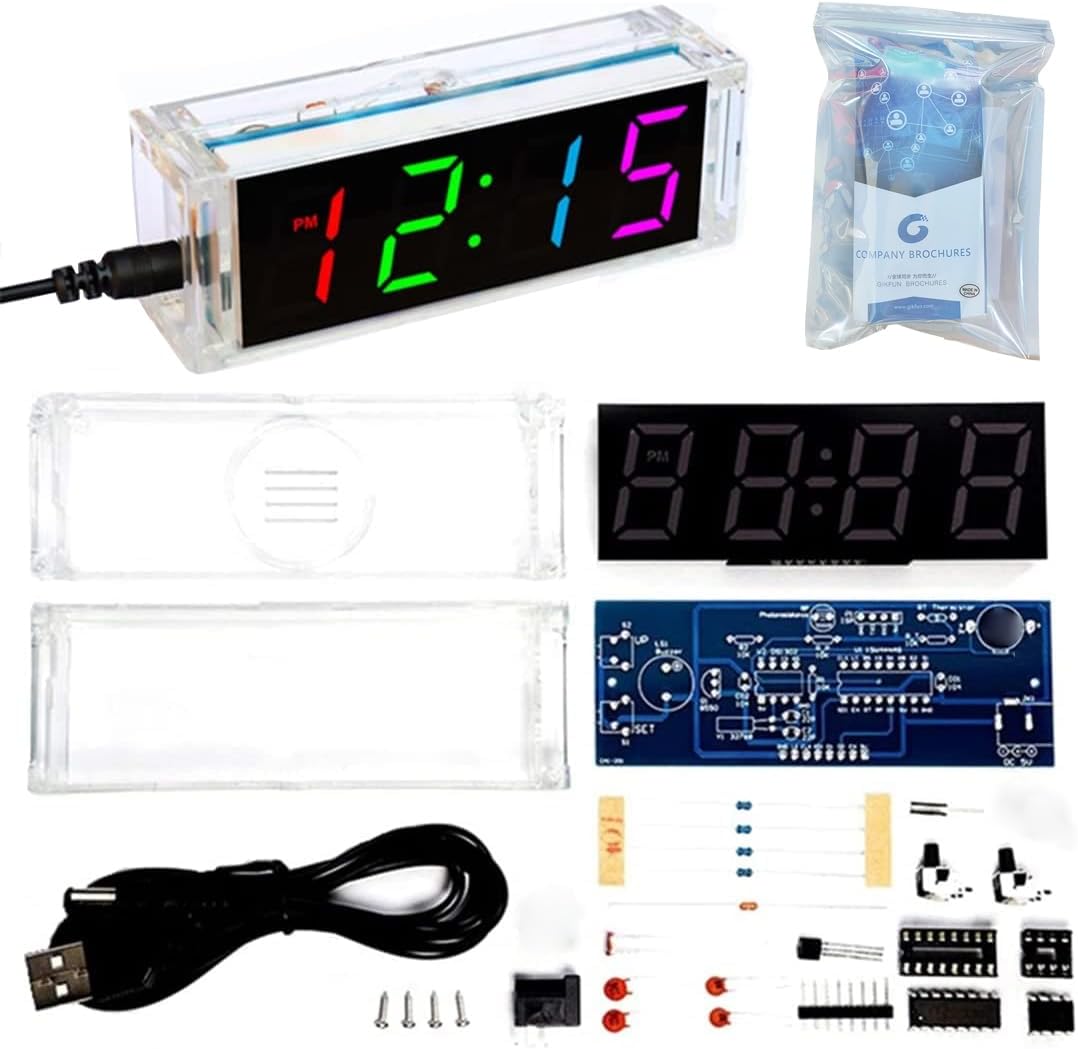
Figure 2: Gikfun EK1973 DIY Clock Kit Components.
4. Montageanleitung
Follow these steps carefully to assemble your digital alarm clock. Refer to the circuit diagram and component placement image for guidance.
4.1. Soldering Tips
- Preheat your soldering iron to an appropriate temperature (typically 300-350°C for leaded solder).
- Tin the iron tip with a small amount of solder.
- Erhitzen Sie gleichzeitig sowohl den Bauteilanschluss als auch die Leiterplattenauflage.
- Apply solder to the heated joint, allowing it to flow smoothly around the lead and pad.
- Entfernen Sie das Lot und anschließend den Lötkolben. Lassen Sie die Lötstelle natürlich abkühlen.
- Ensure components are correctly oriented (e.g., polarity for diodes, ICs).
4.2. Schrittweise Montage
It is recommended to solder components from shortest to tallest to ensure stability during assembly.
- Widerstände installieren: Solder all 10K resistors (R1, R2, R_P_R_T) and 8550 resistors (R_B) into their designated positions on the PCB. Resistors are non-polarized.
- Install Crystal Oscillator: Solder the 32.768KHz crystal oscillator (Y1) into place.
- Install Ceramic Capacitors: Solder the 22pF capacitors (C1, C2) and 104 capacitor (C01) into their positions. Ceramic capacitors are non-polarized.
- Batteriehalter einbauen: Solder the CR1220 battery holder (BT1) onto the PCB. Ensure correct polarity if marked.
- Install Buzzer: Solder the buzzer (LS1) into its position. Pay attention to the positive (+) and negative (-) markings on the PCB and buzzer.
- IC-Sockel installieren: Solder the 16-pin (U1) and 8-pin (U2) IC sockets. Ensure the notch on the socket aligns with the notch on the PCB silkscreen.
- Install Tactile Switches and DC Socket: Solder the SET (S1) and UP (S2) tactile switches and the DC power socket (JK1) into their respective locations.
- Install Photoresistor and Thermistor: Solder the photoresistor (RP) and thermistor (RT) into their positions. Leave a small gap between the component and the PCB.
- Install Digital Tube Pins: Solder the pins for the digital tube display onto the circuit board.
- ICs installieren: Carefully insert the STC15W401AS (U1) and DS1302 (U2) ICs into their corresponding sockets. Ensure the notch on the IC aligns with the notch on the socket and PCB.
- LED-Anzeige anschließen: Carefully align and solder the 4-digit LED display module to the main PCB.
- Zusammenbau Casing: Once all soldering is complete and verified, assemble the acrylic casing around the PCB using the provided screws.

Figure 3: Gikfun EK1973 Assembly Steps.
4.3. Montage-Videoanleitung
Video 1: Step-by-step assembly process for the Gikfun Colorful Digital LED Electronic Alarm Clock DIY Kit, demonstrating soldering and component placement.
5. Bedienungsanleitung
After successful assembly, connect the clock to a 5V DC power supply using the provided USB cable.
5.1. Grundlegende Anzeigefunktionen
- The clock can display Time, Date, and Temperature.
- It features power-off memory, retaining settings even when power is lost.

Figure 4: Key Features of the Gikfun EK1973 Clock.
5.2. Helligkeitseinstellung
The display brightness can be set to automatically adjust based on ambient light, or manually adjusted to your preferred level.
5.3. Color Display Modes
The clock supports various color display modes, including automatic color changes and the ability to set individual colors for each digit.

Abbildung 5: Bspample of multi-color display.
5.4. Uhrzeit und Datum einstellen
Use the 'SET' and 'UP' buttons to navigate through settings and adjust values. Refer to the detailed operation video for specific button press sequences.
5.5. Alarmfunktion
The clock includes an alarm function with three adjustable music options. Set your desired alarm times and choose from the available melodies.
5.6. Operation Video Guide
Video 2: Demonstration of the Gikfun Colorful Digital LED Electronic Alarm Clock's functions, including setting time, date, and alarm.
6. Wartung
- Keep the clock clean and free from dust. Use a soft, dry cloth for cleaning.
- Setzen Sie die Uhr keinen extremen Temperaturen oder Feuchtigkeit aus.
- If the display becomes dim or erratic, check the power connection and ensure the CR1220 backup battery is functional.
7. Fehlerbehebung
- Clock does not power on: Verify the 5V DC power supply is connected correctly and functioning. Check all soldered power connections on the PCB.
- Display is blank or shows incorrect characters: Ensure the LED display module is correctly soldered and seated. Check for any short circuits or cold solder joints. Verify the ICs are correctly inserted into their sockets.
- Tasten reagieren nicht: Check the soldering of the tactile switches. Ensure they are not stuck or damaged.
- Incorrect time/date/temperature: Follow the operating instructions carefully to set the time and date. The temperature sensor may require calibration if readings are consistently inaccurate.
- Der Alarm ertönt nicht: Check alarm settings to ensure it is enabled and the volume is not muted. Verify the buzzer is correctly soldered.
- Difficulty with soldering: This kit requires certain soldering skills. If you are a beginner, consider practicing on a separate soldering practice board before attempting the main circuit. Ensure your soldering iron tip is clean and properly tinned.
8. Spezifikationen
| Besonderheit | Detail |
|---|---|
| Marke | Gikfun |
| Modellnummer | EK1973 |
| Anzeigetyp | Digital LED (4-digit) |
| Anzeigefarbe | Colorful (Multicolor) |
| Funktionen | Time, Date, Temperature, Alarm, Brightness Adjustment, Color Modes, Power-off Memory |
| Stromversorgung | 5V Gleichstrom (USB-Stromversorgung) |
| Pufferbatterie | CR1220 (nicht enthalten) |
| Technische Daten | 4.7 Zoll B x 1.5 Zoll H (ca. 11.5 cm x 4 cm) |
| Material | PCB, Acrylic |
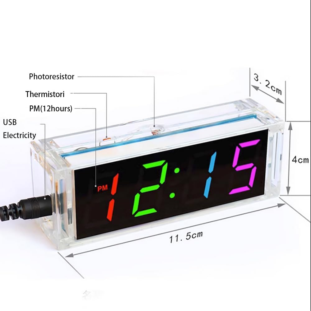
Figure 6: Product Dimensions and Key Components.
9. Garantie und Support
For any issues or questions regarding your Gikfun EK1973 DIY kit, please contact Gikfun customer support through the retailer's platform or visit the official Gikfun website. Please note that this is a DIY soldering kit, and successful operation depends on correct assembly and soldering techniques. Warranty may be limited for self-assembled products.