1. Einleitung
This manual provides comprehensive instructions for the installation, configuration, and operation of your ASUS TUF GAMING B650M-E AMD mATX Motherboard. Please read this manual thoroughly before installing or using the product to ensure proper functionality and to prevent damage.
The ASUS TUF GAMING B650M-E is designed to support AMD Ryzen 7000 Series processors and features an 8+2 DrMOS power solution, DDR5 memory support, PCIe 5.0, and multiple M.2 slots for high-performance storage. It is built for durability and stable performance.
2. Sicherheitshinweise
Beachten Sie die folgenden Sicherheitsvorkehrungen, um Schäden am Motherboard und Verletzungen zu vermeiden:
- Vor dem Berühren von internen Bauteilen muss immer das Netzkabel aus der Steckdose gezogen werden.
- Tragen Sie ein antistatisches Armband oder berühren Sie häufig einen geerdeten Metallgegenstand, um statische Elektrizität abzuleiten, bevor Sie das Motherboard oder andere Komponenten handhaben.
- Fassen Sie das Motherboard an den Kanten an, um eine Berührung empfindlicher Bauteile zu vermeiden.
- Stellen Sie sicher, dass alle Kabel korrekt und sicher angeschlossen sind, bevor Sie das System einschalten.
- Das Motherboard sollte vor Feuchtigkeit und extremen Temperaturen geschützt werden.
3. Packungsinhalt
Verify that all items are present in your motherboard package. If any item is damaged or missing, contact your retailer.
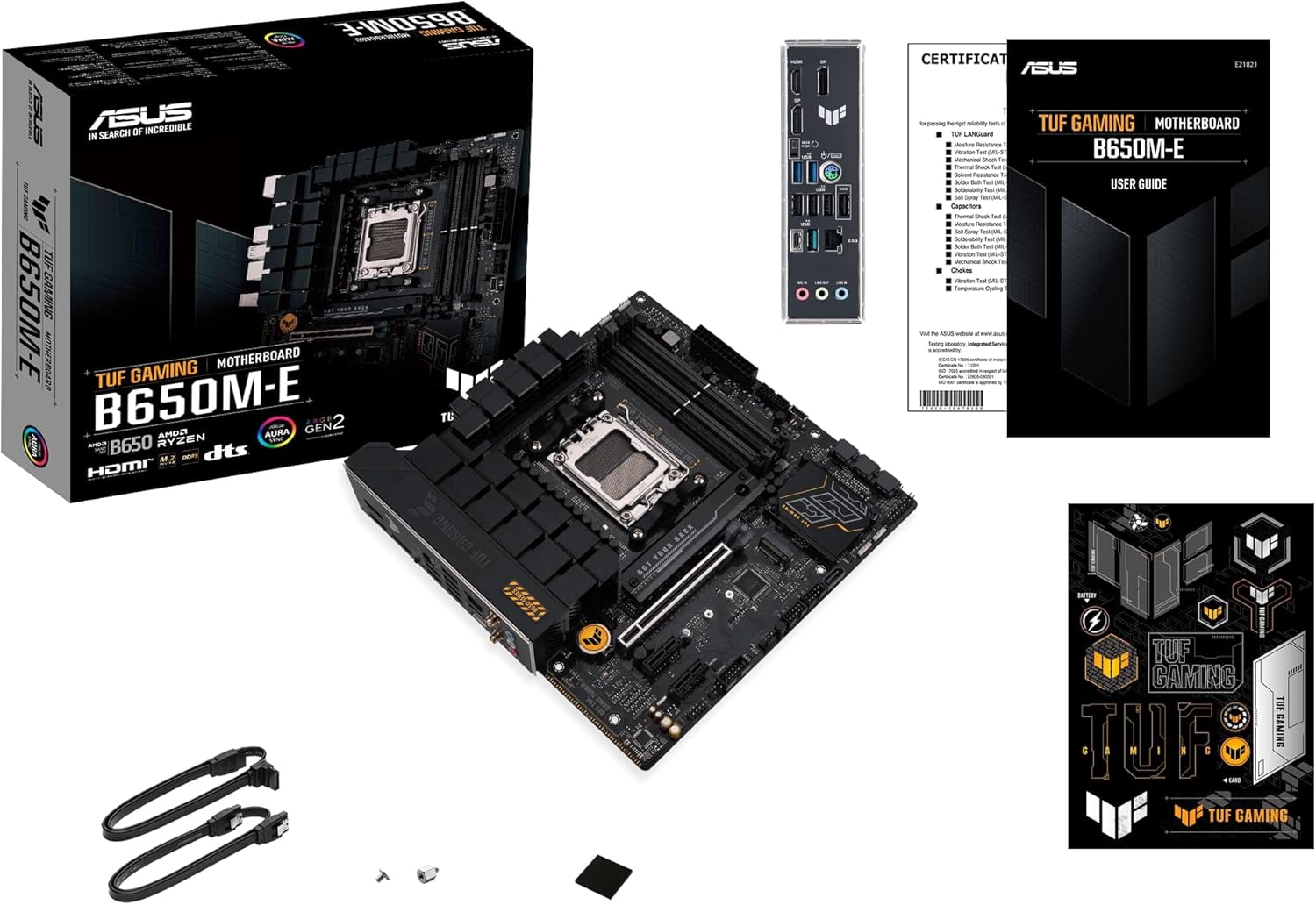
Bild 3.1: Contents of the ASUS TUF GAMING B650M-E package. This image displays the motherboard, user guide, SATA cables, M.2 screws, and TUF Gaming stickers.
- ASUS TUF GAMING B650M-E Motherboard
- Benutzerhandbuch
- SATA-6-Gb/s-Kabel
- M.2 SSD screw package
- TUF Gaming stickers
4. Motherboard-Layout
Machen Sie sich vor der Installation mit den verschiedenen Komponenten und Anschlüssen auf dem Motherboard vertraut.
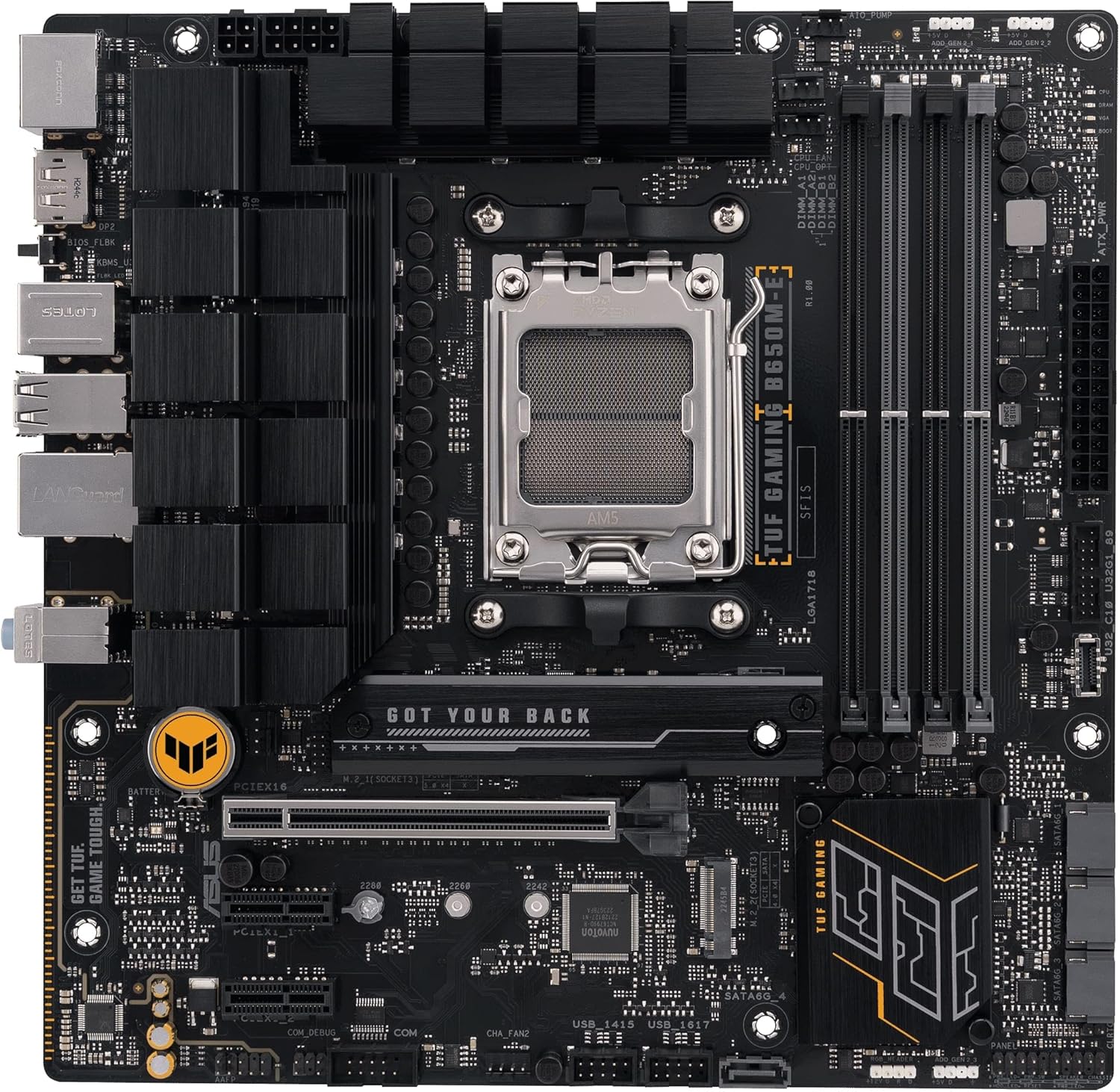
Bild 4.1: Von oben nach unten view of the ASUS TUF GAMING B650M-E motherboard, highlighting the CPU socket, DIMM slots, PCIe slots, and M.2 slots.
4.1. Rückseitige I/O-Leiste
Das rückseitige I/O-Panel bietet verschiedene Anschlüsse zum Verbinden externer Geräte.

Bild 4.2: Nahaufnahme view of the rear I/O panel, showing ports for USB, DisplayPort, HDMI, LAN, and audio.
- DisplayPort (DP): For connecting display devices.
- HDMI: For connecting display devices.
- USB 2.0 Ports: Zum Anschluss von Peripheriegeräten.
- USB 3.2 Gen 1 Anschlüsse: Zum Anschluss von Hochgeschwindigkeits-USB-Geräten.
- USB 3.2 Gen 2 Typ-C-Anschluss: For connecting USB Type-C devices.
- 2.5 Gb Ethernet Port: Für die Netzwerkkonnektivität.
- Audiobuchsen: For connecting audio devices (Line In, Line Out, Mic In).
- BIOS FlashBack-Taste: Zum Aktualisieren des BIOS ohne CPU oder RAM.
5. Einrichtung und Installation
Follow these steps to install the motherboard and its components into your PC case.
5.1. CPU-Installation
- Suchen Sie den AM5-CPU-Sockel auf dem Motherboard.
- Öffnen Sie den Hebel des CPU-Sockels und entfernen Sie die Schutzabdeckung.
- Richten Sie die CPU sorgfältig am Sockel aus und achten Sie darauf, dass die dreieckige Markierung auf der CPU mit der Markierung auf dem Sockel übereinstimmt.
- Setzen Sie die CPU vorsichtig und ohne Kraftaufwand in den Sockel ein.
- Schließen Sie den Sockelhebel, um die CPU zu sichern.
- Installieren Sie den CPU-Kühler gemäß den Anweisungen des Herstellers.
5.2. Installation des Arbeitsspeichers (RAM)
Dieses Mainboard unterstützt DDR5-Speichermodule. Eine Liste kompatibler Speichermodule finden Sie in der QVL (Qualified Vendor List) des Mainboards.
- Öffnen Sie die Klemmen an beiden Enden der DIMM-Steckplätze.
- Richten Sie die Kerbe am DDR5-Speichermodul an der entsprechenden Aussparung im DIMM-Steckplatz aus.
- Schieben Sie das Speichermodul fest in den Steckplatz, bis die Halteklammern einrasten.
- For dual-channel configuration, install modules into the recommended slots (usually A2 and B2).
5.3. Storage (M.2 and SATA) Installation
M.2-SSD-Installation
- Suchen Sie die M.2-Steckplätze auf dem Motherboard.
- Remove the M.2 heatsink (if present) and the standoff screw.
- Setzen Sie die M.2 SSD in einem Winkel von 30 Grad in den Steckplatz ein.
- Drücken Sie die M.2 SSD vorsichtig nach unten und fixieren Sie sie mit der Abstandsschraube.
- Reinstall the M.2 heatsink (if applicable).
SATA-Geräteinstallation
- Verbinden Sie ein Ende des SATA-Datenkabels mit einem SATA-Anschluss auf dem Motherboard.
- Connect the other end of the SATA data cable to your SATA storage device (HDD/SSD).
- Connect a SATA power cable from your power supply unit (PSU) to the SATA storage device.
5.4. Expansion Card (PCIe) Installation
This motherboard features PCIe 5.0 x16 and other PCIe slots for graphics cards and other expansion cards.
- Suchen Sie den gewünschten PCIe-Steckplatz.
- Entfernen Sie die entsprechende Erweiterungssteckplatzabdeckung von Ihrem PC-Gehäuse.
- Richten Sie die Erweiterungskarte am Steckplatz aus und drücken Sie sie fest nach unten, bis sie richtig sitzt.
- Befestigen Sie die Karte mit einer Schraube oder dem Haltemechanismus des Gehäuses.
5.5. Stromanschlüsse
Schließen Sie die Kabel des Netzteils (PSU) an das Motherboard an.
- 24-poliger ATX-Stromanschluss: Connect the main 24-pin power cable from the PSU.
- 8-pin + 4-pin ATX 12V Power Connectors: Connect the CPU power cables from the PSU. Ensure both are connected for stable power delivery, especially with high-end CPUs.
5.6. Anschlüsse an der Vorderseite
Connect the cables from your PC case's front panel to the corresponding headers on the motherboard.
- Front Panel Header (F_PANEL): For power button, reset button, HDD LED, and power LED. Refer to the user guide for pin assignments.
- USB-Header: Connect front panel USB ports (USB 2.0, USB 3.2 Gen 1, USB 3.2 Gen 2 Type-C).
- Front Panel Audio Header (AAFP): For front panel headphone and microphone jacks.
6. Bedienungsanleitung
6.1. BIOS/UEFI-Einrichtung
The BIOS (Basic Input/Output System) or UEFI (Unified Extensible Firmware Interface) is firmware that initializes hardware during the booting process and provides runtime services for the operating system. You can access the BIOS/UEFI setup utility to configure system settings.
- Zugriff auf BIOS/UEFI: During system startup, press the Löschen Schlüssel oder F2 Taste wiederholt.
- Navigation: Verwenden Sie die Pfeiltasten zur Navigation und Eingeben to select. Many ASUS UEFI interfaces also support mouse input.
- Tasteneinstellungen:
- Reihenfolge der Stiefel: Konfigurieren Sie die Reihenfolge der Speichergeräte für den Start des Betriebssystems.
- Overclocking (OC) Settings: CPU- und Speicherfrequenzen/Lautstärke anpassentages (use with caution).
- Lüftersteuerung: Monitor and adjust fan speeds.
- SATA-Konfiguration: Set SATA mode (AHCI/RAID).
- Änderungen speichern: Always save changes before exiting the BIOS/UEFI setup.
6.2. Treiberinstallation
After installing your operating system, install the necessary drivers for optimal performance and functionality. Drivers can be found on the ASUS support webWebseite für Ihr Motherboard-Modell.
- Chipsatztreiber: Essential for motherboard functionality.
- LAN-Treiber: Für die Netzwerkkonnektivität.
- Audiotreiber: For sound output and input.
- Grafiktreiber: If using integrated graphics or a dedicated GPU.
- USB-Treiber: For optimal USB device performance.
6.3. Software-Dienstprogramme
ASUS provides various software utilities to enhance your user experience:
- Waffenkammerkiste: Eine zentrale Schaltstelle für die Verwaltung von Treibern, Hilfsprogrammen und Aura Sync-Beleuchtung.
- Aura-Synchronisierung: Zur individuellen Anpassung von RGB-Beleuchtungseffekten auf kompatiblen Komponenten.
- KI-Rauschunterdrückung: Enhances audio clarity for communication.
7. Wartung
7.1. BIOS-Updates
Regularly updating your BIOS can improve system stability, compatibility, and performance. Visit the ASUS support webWebsite für die neuesten BIOS-Versionen und Update-Anweisungen.
- EZ Flash 3: Update BIOS directly from the UEFI interface using a USB flash drive.
- BIOS FlashBack: Update BIOS without a CPU or RAM installed by using the dedicated USB port and button on the rear I/O panel.
7.2. Reinigung
To ensure optimal performance and longevity, periodically clean your motherboard and PC case.
- Disconnect all power before cleaning.
- Verwenden Sie Druckluft, um Staub von Kühlkörpern, Lüftern und anderen Bauteilen zu entfernen.
- Verwenden Sie ein weiches, fusselfreies Tuch, um die Oberflächen vorsichtig abzuwischen. Vermeiden Sie die direkte Anwendung von flüssigen Reinigungsmitteln auf den Bauteilen.
8. Fehlerbehebung
In diesem Abschnitt werden häufig auftretende Probleme behandelt.
| Problem | Mögliche Lösung |
|---|---|
| Das System lässt sich nicht einschalten. |
|
| Keine Displayausgabe. |
|
| System reboots or crashes randomly. |
|
| Betriebssystem nicht erkannt. |
|
9. Spezifikationen
Key technical specifications for the ASUS TUF GAMING B650M-E Motherboard.
| Besonderheit | Detail |
|---|---|
| Marke | ASUS |
| Modellname | TUF Gaming B650M-E |
| CPU-Sockel | Sockel AM5 |
| Kompatible Prozessoren | AMD Ryzen 7000 Series (and future compatible generations) |
| Chipsatztyp | AMD B650 |
| RAM-Speichertechnologie | DDR5 |
| Speichertaktfrequenz | Up to 2400 MHz (JEDEC), higher with EXPO/OC |
| PCIe-Steckplätze | 1 x PCIe 5.0 x16, additional PCIe slots |
| M.2-Steckplätze | 2 x M.2 slots |
| LAN | 2.5-Gbit-Ethernet |
| Videoausgang | 2 x DisplayPort, 1 x HDMI |
| USB-Anschlüsse | USB 2.0, USB 3.2 Gen 1, USB 3.2 Gen 2 Type-C |
| Formfaktor | mATX |
| Artikelgewicht | 2.2 Pfund |
10. Garantie und Support
For detailed warranty information, please refer to the warranty card included in your product package or visit the official ASUS webWebsite.
ASUS-Support: For technical assistance, driver downloads, and further information, please visit the official ASUS support webWebsite: www.asus.com/support/
When contacting support, please have your motherboard model (TUF GAMING B650M-E) and serial number ready.