
1. Einleitung
This manual provides essential information for the proper installation, operation, and maintenance of your Bisida 23S 72V 50A Lifepo4 Battery Management System (BMS). This BMS is designed to protect 23-series 72V Lifepo4 battery packs, ensuring their longevity and safe operation. Please read these instructions carefully before use.
2. Hauptmerkmale
The Bisida 23S 72V 50A BMS incorporates advanced protection features and high-quality components to safeguard your battery pack.
- Mehrere Schutzfunktionen: Includes overcharge protection, over-discharge protection, overcurrent protection, short-circuit protection, temperature protection, and downtime protection.
- Bandtage Balance: Features passive balance to maintain cell voltage consistency, extending battery life.
- Großer Betriebstemperaturbereich: Supports Lifepo4 battery charging and discharging from -20°C to 70°C.
- Hochwertige Komponenten: Manufactured with excellent protective integrated circuit (IC) and Mosfet for robustness and reliability.
- NTC Temperature Control Probe: Equipped with a new generation NTC temperature control probe for precise temperature monitoring.

Abbildung 2.1: Überview of the ten functional protections integrated into the BMS.
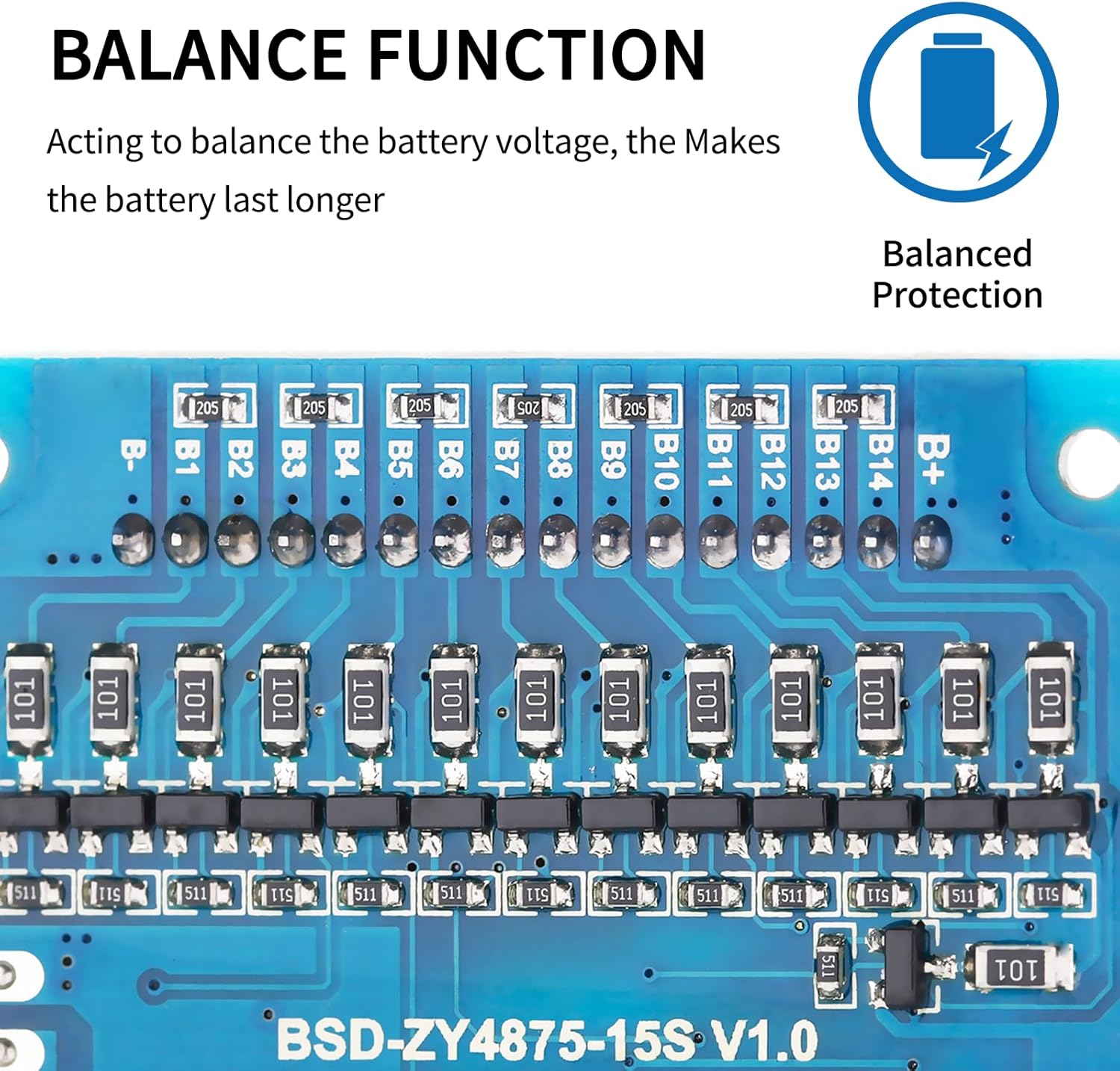
Figure 2.2: NTC temperature control probe for accurate temperature monitoring.

Figure 2.3: Balance function components on the BMS board, ensuring balanced cell voltages.
3. Installations- und Verdrahtungsanleitung
Proper wiring is critical for the safe and correct operation of the BMS. Incorrect wiring can damage the BMS, battery pack, or connected devices. Always ensure the battery cells are balanced before connecting the BMS.
3.1 Pre-installation Notice
Before installing the BMS protective board, it is essential to match the voltage, capacity, and internal resistance of individual battery cells. The voltage difference between cells should not exceed 0.05V, the internal resistance difference should not be more than 5mΩ, and the capacity difference should be less than 30mAh. Failure to meet these conditions may prevent the battery pack from charging correctly.
3.2 Wiring Method for Common Port BMS
Follow these steps for wiring your BMS:
- Verbinden Sie B- terminal of the BMS to the negative terminal of the battery pack.
- Verbinden Sie C- terminal of the BMS to the negative terminal for both charging and discharging output.
- All positive electrodes of the battery cells should be connected to the total positive pole of the battery pack.
- Connect the balance wires sequentially, starting from the black wire (B0 or B-) and proceeding in ascending order of voltage (B1, B2, B3, etc.) up to B+. Ensure each balance wire is connected to its corresponding cell tap.

Abbildung 3.1: Bspample wiring diagram for a serial number connection. This analogy can be extended to other serial protection board wiring methods.
Wichtig: Um Schäden zu vermeiden, sollten Sie vor dem Einschalten stets alle Verbindungen doppelt prüfen.
4. Betriebsbedingungen
The Bisida BMS is designed for Lifepo4 batteries with a nominal voltage of 3.2V per cell. The charging and discharging voltage zones are from 2.3V to 3.65V per cell.
- Schutz bei niedrigen Temperaturen: Activates at -20°C.
- Hochtemperaturschutz: Activates at 70°C.
Specific parameter details may vary with different voltages and currents. Refer to the specifications table for precise values.
5. Spezifikationen
The following table outlines the key technical specifications and protection parameters for the Bisida 23S 72V 50A Lifepo4 BMS.

Figure 5.1: Lifepo4 Data and Protection Parameters. Note: Internal resistance and self-consumption are dynamic. Test items marked with '*' mean mass production product sampling item or reference item; 'O' indicates the product does not have this function or is not controlled.
| Attribut | Wert |
|---|---|
| Modellname | 23S 72V 50A |
| Bandtage | 72 V |
| Produktabmessungen (L x B x H) | 5 x 2 x 2 Zoll |
| Artikelgewicht | 6.7 Unzen |
| Hersteller | Bisida |
| Einheitenanzahl | 1.0 Anzahl |
6. Wartung
To ensure optimal performance and longevity of your BMS and battery pack, consider the following maintenance guidelines:
- Regelmäßige Inspektion: Überprüfen Sie regelmäßig alle Drahtverbindungen auf festen Sitz und Anzeichen von Korrosion oder Beschädigung.
- Umgebungsbedingungen: Betreiben Sie das Gebäudeleitsystem innerhalb des spezifizierten Temperaturbereichs. Vermeiden Sie den Kontakt mit extremen Temperaturen, Feuchtigkeit oder Staub.
- Zellausgleich: The BMS provides passive balancing. For long-term health, ensure your battery cells are well-matched in voltage, capacity, and internal resistance during initial assembly.
- Reinigung: If necessary, gently clean the BMS board with a dry, soft brush to remove any dust accumulation. Do not use liquids.
7. Fehlerbehebung
If you encounter issues with your BMS, refer to the following common troubleshooting steps:
7.1 Battery Pack Not Charging
- Check Cell Matching: Stellen Sie sicher, dass die Lautstärketage, capacity, and internal resistance of individual battery cells meet the pre-installation requirements (voltage difference < 0.05V, internal resistance difference < 5mΩ, capacity difference < 30mAh). Significant discrepancies can prevent charging.
- Verkabelung überprüfen: Double-check all wiring connections, especially B-, C-, and the balance wires, according to the wiring diagram (Figure 3.1). Loose or incorrect connections are a common cause of issues.
- Auf Schäden prüfen: Look for any visible damage to the BMS board, wires, or battery cells.
- Temperaturschutz: Ensure the battery pack and BMS are operating within the specified temperature range (-20°C to 70°C). Extreme temperatures can trigger protection modes.
7.2 Overcurrent or Short-Circuit Protection Triggered
- Last reduzieren: If overcurrent protection is triggered, reduce the load connected to the battery pack.
- Prüfen Sie auf Shorts: Immediately disconnect power and inspect all connections and devices for any short circuits.
- Zurücksetzen: Some protections may automatically reset once the fault condition is removed. If not, a power cycle (disconnecting and reconnecting the battery pack) might be necessary after ensuring safety.
Sollten die Probleme nach Durchführung dieser Schritte weiterhin bestehen, wenden Sie sich bitte an den Kundendienst, um weitere Unterstützung zu erhalten.
8. Garantie und Support
Bisida products are manufactured to high-quality standards. For warranty information or technical support, please refer to the product packaging or contact your retailer. Keep your purchase receipt as proof of purchase.