SEAFRONT SEAFRONTqbks9m7dhv
SEAFRONT 1.1kW Variable Frequency Drive (VFD) User Manual
Model: SEAFRONTqbks9m7dhv
1. Einleitung
This manual provides essential information for the safe and efficient operation of your SEAFRONT 1.1kW Variable Frequency Drive (VFD). Please read this manual thoroughly before installation, operation, or maintenance to ensure proper usage and prevent potential hazards. Keep this manual for future reference.
The SEAFRONT VFD is designed to control the speed of 3-phase motors, converting a single-phase input (176-264V) into a three-phase output (0-220V) with a frequency range of 0.1-400Hz. It features V/F control, vector control, and output torque control, along with an external LED digital display panel for easy monitoring and adjustment.

Abbildung 1: Vorderseite view of the SEAFRONT 1.1kW VFD, showing the LED display, control buttons (PROG, RUN, STOP, OK, UP, DOWN), and a rotary knob for frequency adjustment.
2. Sicherheitshinweise
Beachten Sie stets die folgenden Sicherheitsvorkehrungen, um Verletzungen oder Schäden an der Ausrüstung zu vermeiden:
- Installation und Verkabelung dürfen nur von qualifiziertem Fachpersonal durchgeführt werden.
- Vor jeglichen Verkabelungs- oder Wartungsarbeiten muss die Stromversorgung unterbrochen sein.
- Do not touch the terminals while power is applied or shortly after power is removed, as residual voltagEs können welche vorhanden sein.
- The VFD enclosure is made of flame-retardant PC material, providing good insulation. However, proper grounding is essential.
- Do not operate the VFD with damaged cables or if the enclosure is open.
- Protect the VFD from moisture, dust, direct sunlight, and corrosive gases.
3. Produktüberschreitungview und Funktionen
The SEAFRONT 1.1kW VFD is a compact and robust motor speed controller designed for various industrial applications. Key features include:
- Mehrere Steuerungsmodi: Supports V/F control, vector control, and output torque control for versatile motor management.
- Langlebige Konstruktion: Features a flame-retardant PC enclosure for good insulation and environmental protection.
- High Performance Coils: Utilizes copper core coils for strong resistance, stable performance, and high load capacity.
- Großer Frequenzbereich: Operates within a frequency range of 0.1-400Hz.
- External LED Display: Equipped with an external LED digital display panel for clear status indication and parameter adjustment.
- Kompaktes Design: Small size with high torque output, suitable for various applications.
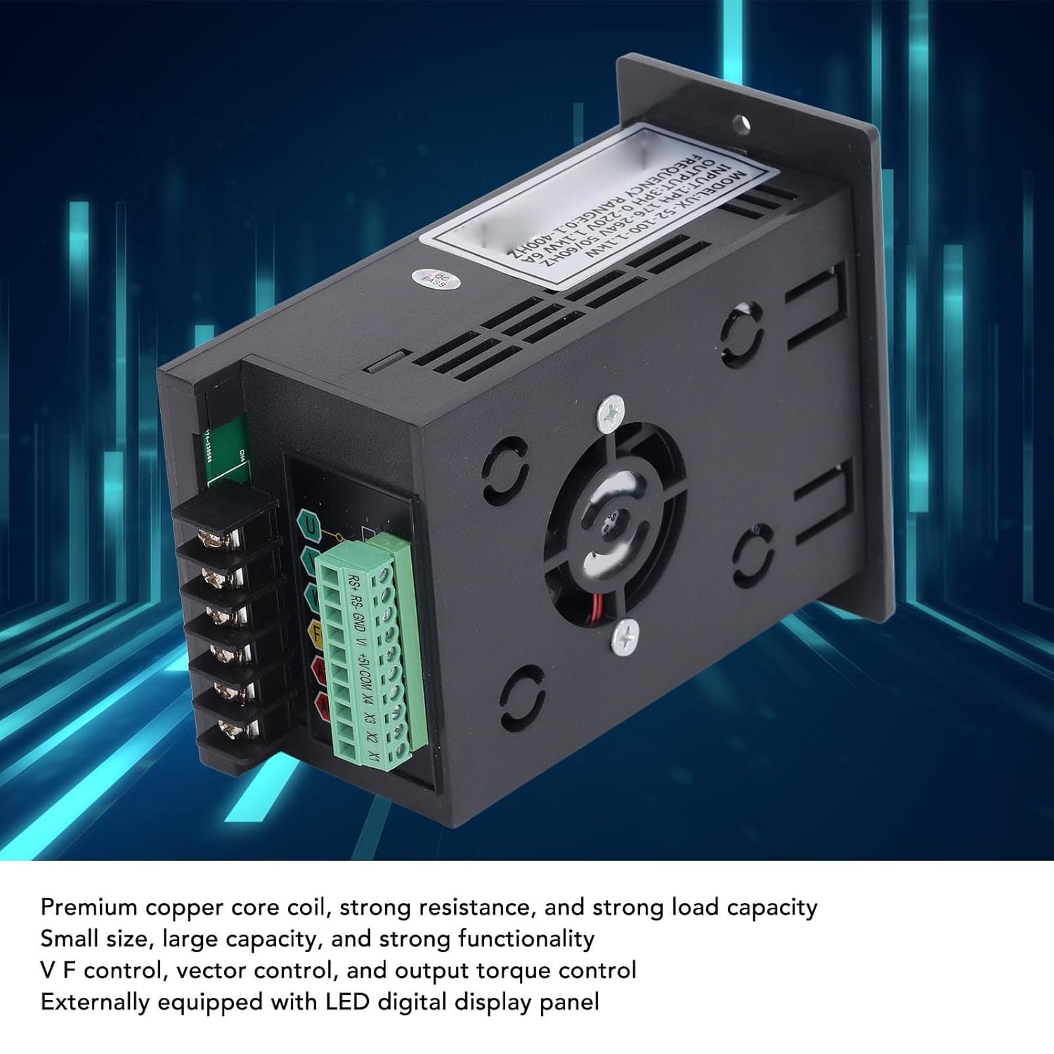
Figure 2: Internal components of the VFD, highlighting the premium copper core coils for stable performance and the integrated cooling fan.
4. Einrichtung und Installation
4.1 Auspacken und Prüfen
Upon receiving the VFD, carefully unpack it and inspect for any signs of damage during transit. Verify that all components are present according to the packing list (if provided). If any damage or missing parts are found, contact your supplier immediately.
4.2 Montage
Mount the VFD in a vertical position on a flat, stable surface. Ensure adequate ventilation around the unit to prevent overheating. Maintain sufficient clearance from other equipment and walls for proper airflow. Avoid mounting in areas with excessive vibration, dust, or direct heat sources.
4.3 Verkabelung
All wiring must comply with local electrical codes and safety regulations. Ensure the main power supply is disconnected before proceeding with any wiring.
- Leistungsaufnahme (Wechselstrom): Connect the single-phase 176-264V AC power supply to the "AC" terminals. Ensure correct polarity if applicable, though AC typically does not have strict polarity.
- Motorleistung (U, V, W): Connect the three-phase motor leads to the "U", "V", and "W" output terminals.
- Ground (FG): Connect the frame ground (FG) terminal to a reliable earth ground. This is crucial for safety.
- Control Terminals (RS+, RS-, GND, V+, +5V, COM, X1, X2, X3, X4): These terminals are for external control signals, such as remote start/stop, speed reference (analog input V+), and digital inputs (X1-X4). Refer to the detailed wiring diagram for specific connections based on your application.

Figure 3: Wiring terminals on the VFD, including AC input, U/V/W motor output, FG ground, and control terminals.
5. Bedienungsanleitung
5.1 Erstes Einschalten
After completing all wiring and safety checks, apply power to the VFD. The LED display should illuminate, indicating the unit is powered on. The display will typically show the current frequency or a default parameter.
5.2 Grundlegende Bedienung
- Start/Stopp: Drücken Sie die LAUFEN Knopf zum Starten des Motors und der STOPPEN Taste, um es zu stoppen.
- Frequenzanpassung: Use the rotary knob on the front panel to adjust the output frequency, which directly controls the motor speed. Turn clockwise to increase frequency, counter-clockwise to decrease.
- Parameter Navigation: Verwenden Sie die PROG button to enter the parameter setting mode. Use the UP Und RUNTER buttons to navigate through parameters. Press OK to select a parameter and confirm changes.
5.3 Advanced Control Settings
The VFD offers various programmable parameters for fine-tuning motor control. These include acceleration/deceleration times, maximum/minimum frequencies, V/F curve settings, and input/output terminal configurations. Refer to the detailed parameter list in the full technical manual for advanced programming.
Example Anwendungen: The VFD is suitable for a wide range of equipment, including fans, water pumps, automated machine tools, and engraving machines.

Figure 4: Common application scenarios for the SEAFRONT VFD, demonstrating its versatility in industrial and automated settings.
6. Wartung
Regular maintenance helps ensure the longevity and reliable operation of your VFD. Always disconnect power before performing any maintenance.
- Reinigung: Reinigen Sie regelmäßig die Außenseite und die Lüftungsöffnungen des Frequenzumrichters, um Staubablagerungen zu vermeiden, die die Kühlung beeinträchtigen können. Verwenden Sie dazu ein weiches, trockenes Tuch. Verwenden Sie keine flüssigen Reinigungsmittel.
- Lüfterinspektion: Check the cooling fan for proper operation and ensure it is free from obstructions. Replace the fan if it becomes noisy or stops working.
- Anschlussdichtheit: Periodically check all terminal connections for tightness. Loose connections can cause overheating and intermittent operation.
- Umweltcheck: Stellen Sie sicher, dass die Betriebsumgebung innerhalb der vorgegebenen Temperatur- und Feuchtigkeitsbereiche bleibt.
7. Fehlerbehebung
This section provides solutions to common issues. For problems not listed here or if issues persist, contact technical support.
| Problem | Mögliche Ursache | Lösung |
|---|---|---|
| Der Frequenzumrichter schaltet sich nicht ein | No input power; incorrect wiring; blown fuse. | Check power supply; verify wiring connections; inspect fuses. |
| Motor startet nicht | Incorrect control signal; motor wiring error; VFD in fault state. | Check RUN command; verify motor connections (U, V, W); check VFD display for error codes. |
| Motorgeschwindigkeit instabil | Improper V/F curve setting; motor load fluctuations; interference. | Adjust V/F parameters; ensure stable load; check for electromagnetic interference. |
| Überstrom-/Überlastfehler | Motor overloaded; acceleration time too short; short circuit in motor wiring. | Reduce motor load; increase acceleration time; check motor and wiring for shorts. |
8. Spezifikationen
| Parameter | Wert |
|---|---|
| Modellnummer | SEAFRONTqbks9m7dhv |
| Eingangslautstärketage | 1PH 176-264V |
| Ausgangsvolumentage | 3PH 0-220V |
| Nennleistung | 1.1 kW |
| Nennstrom | 6A |
| Frequenzbereich | 0.1-400 Hz |
| Steuerungsmodi | V/F control, Vector control, Output torque control |
| Gehäusematerial | Flammhemmendes PC |
| Anzeige | External LED Digital Display Panel |

Figure 5: Dimensional drawing of the VFD, indicating measurements for installation planning.
9. Garantie und Support
This product comes with a standard manufacturer's warranty. For specific warranty terms and conditions, please refer to the documentation provided with your purchase or contact your retailer. For technical support, troubleshooting assistance, or spare parts inquiries, please contact SEAFRONT customer service or your authorized distributor.
Notiz: Availability of spare parts information is currently unavailable. Please contact support for assistance.
Ask a question about this manual
Ask about setup, troubleshooting, compatibility, parts, safety, or missing instructions. Manuals+ will review the question and use this page’s manual context to help answer it.