
1. Einleitung
The BSIDE DC Clamp Meter ACM91 is a versatile digital multimeter designed for precise electrical measurements. It features true RMS auto-ranging capabilities, a 6000-count display, and a range of functions including AC/DC current, voltage, frequency, temperature, capacitance, and resistance. This manual provides essential information for the safe and effective use of your device.
Hauptmerkmale:
- Measures AC/DC current with 1mA resolution via jaws.
- Measures microamps (µA) with 0.1µA resolution via terminals.
- Misst AC/DC-Voltage, frequency, temperature, resistance, continuity, and capacitance.
- V-alert measurement and live-wire check for enhanced safety.
- Low Impedance (LoZ) voltage measurement to eliminate ghost voltages.
- Auto-ranging, auto power off, data hold, and low battery indication with backlight.
- Conforms to IEC-61010-1, IEC-61010-2-030, IEC-61010-2-032, IEC-61010-2-033 standards.
- Überlautstärketage protection class CAT III 300V, CAT II 600V, pollution degree II.
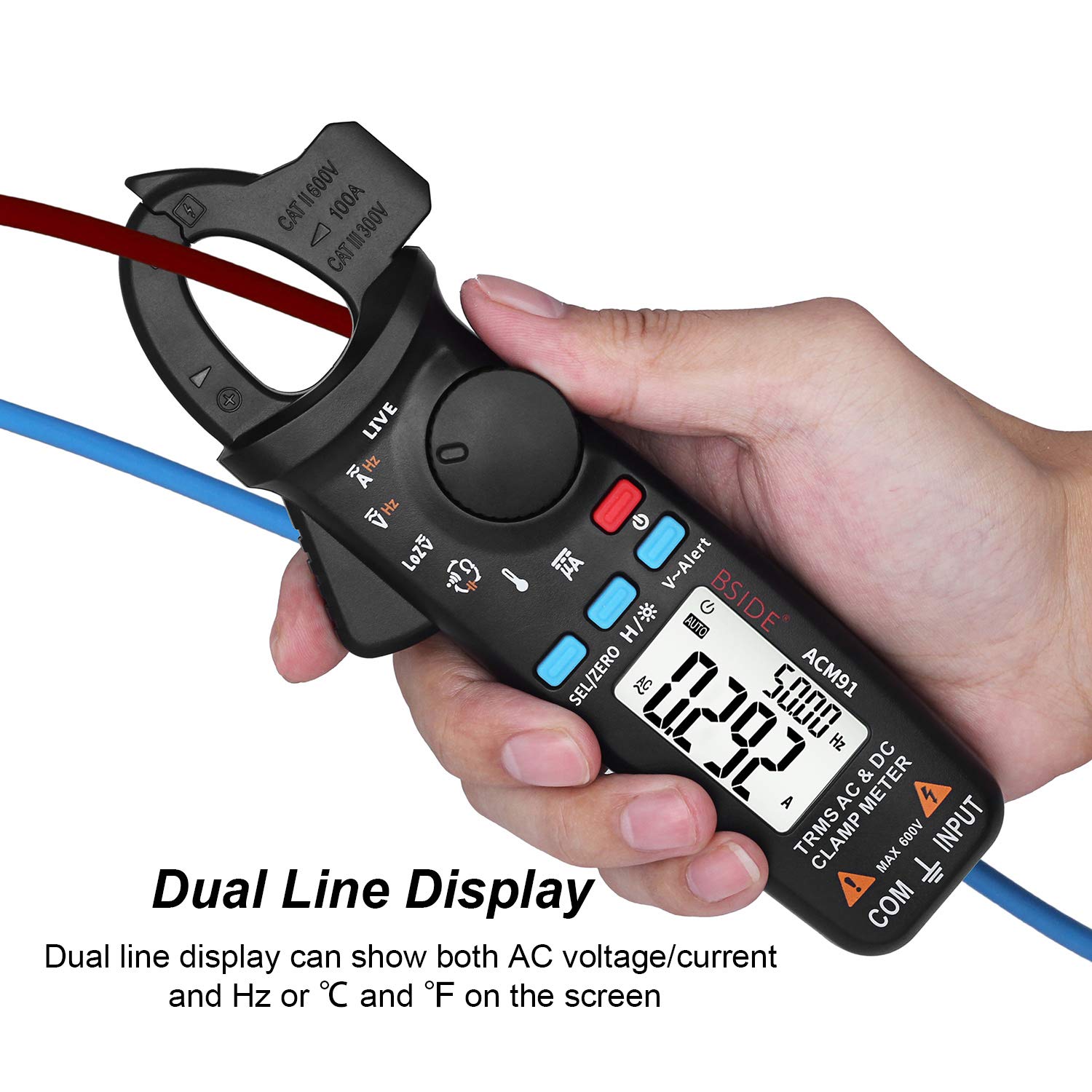
- Dual line display for simultaneous viewing of multiple parameters.
- Integrated back clip for convenient portability.
2. Packungsinhalt
Bitte prüfen Sie, ob alle unten aufgeführten Artikel in Ihrem Paket enthalten sind. Sollten Artikel fehlen oder beschädigt sein, kontaktieren Sie bitte unseren Kundenservice.
- 1 x BSIDE DC Clamp Meter ACM91
- 1 x Paar Messleitungen (rot und schwarz)
- 1 x Thermoelement (Temperaturfühler)
- 1 x Tragetasche
- 1 x Schraubendreher
- 1 x Benutzerhandbuch (dieses Dokument)
Notiz: 2 AAA batteries are required for operation and are not included in the package due to aviation security regulations.

3. Einrichtung
3.1 Einlegen der Batterie
- Stellen Sie sicher, dass das Messgerät ausgeschaltet ist.
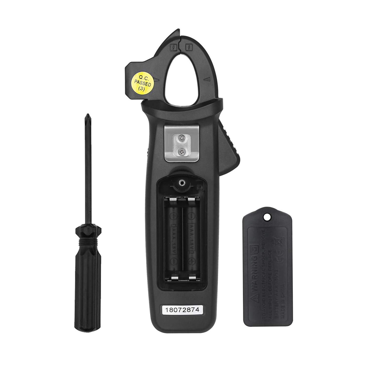
- Suchen Sie den Batteriefachdeckel auf der Rückseite des Messgeräts.
- Verwenden Sie den mitgelieferten Schraubendreher, um die Schraube zu lösen, mit der die Batterieabdeckung befestigt ist.
- Entfernen Sie die Batterieabdeckung.
- Legen Sie zwei 1.5V AAA-Batterien ein und achten Sie dabei auf die richtige Polarität (+/-), wie im Batteriefach angegeben.
- Replace the battery cover and tighten the screw with the screwdriver.
3.2 Anschließen der Testleitungen
Für voltage, resistance, capacitance, frequency (via terminals), microamp current, and temperature measurements, connect the test leads as follows:
- Legen Sie den Rot Testleitung in die EINGANG Terminal.
- Legen Sie den Schwarz Testleitung in die COM (common) terminal.

4. Bedienungsanleitung
4.1 Ein-/Ausschalten
Drücken Sie die Netztaste () to turn the meter on or off. The meter features an auto power-off function to conserve battery life.
4.2 Funktionsauswahl
Rotate the central dial to select the desired measurement function (e.g., AC/DC current, voltage, resistance, temperature). Use the SEL/ZERO button to switch between AC/DC modes or other sub-functions within a dial setting.
4.3 Wechsel-/Gleichstrommessung (Clamp)
- Drehen Sie den Drehschalter auf die A~ (Wechselstrom) oder A= (Gleichstrom) Position.
- Drücken Sie die SEL/ZERO button to select between AC and DC current if necessary. For DC current, press and hold the SEL/ZERO button to zero out the reading before measurement.
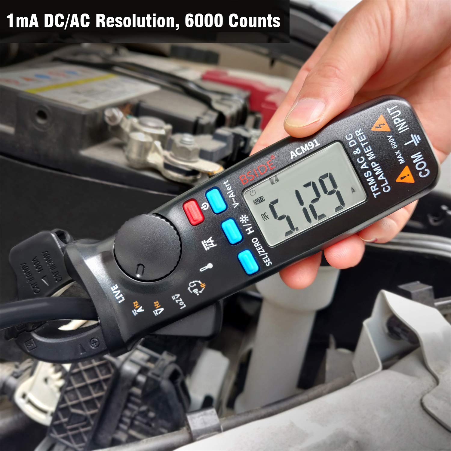
- Öffne dieamp jaws and enclose a single conductor (not a bundle of wires) through the center of the jaws.
- Read the current value on the display. The meter provides 1mA resolution.

4.4 Voltage Messung (AC/DC)
- Schließen Sie die Messleitungen wie in Abschnitt 3.2 beschrieben an.
- Drehen Sie den Drehschalter auf die V~ (AC Voltage) oder V= (DC-Voltage) Position.
- Drücken Sie die SEL/ZERO Taste zum Umschalten zwischen Wechsel- und Gleichstromlautstärketage.
- Berühren Sie mit den Messspitzen die Schaltkreispunkte, an denen die Spannungtage soll gemessen werden.
- Lesen Sie den Bandtage-Wert auf dem Display.
4.5 Low Impedance Voltage (LoZ) Measurement
The LoZ function helps to identify and eliminate ghost or stray voltages that can provide misleading readings. Rotate the dial to the LoZ V~ position and connect the test leads to the circuit. The meter will display the true voltage by presenting a low impedance load.
4.6 V-Alarm (kontaktloser Vol)tage Erkennung)
The V-Alert function allows for non-contact voltage detection. This function can be activated from any measurement mode. Press the V-Alert button. Bring the top of the clamp Das Messgerät befindet sich in der Nähe eines stromführenden Leiters. Es zeigt das Vorhandensein von Wechselspannung an.tage durch akustische Signale und visuelle Anzeigen auf dem Display.

4.7 Prüfung auf stromführende Leitungen
To perform a live wire check, rotate the dial to the LIVE position. Connect the red test lead to the INPUT terminal. Touch the red probe to the conductor you wish to test. The meter will indicate if the wire is live.
4.8 Other Measurements (Resistance, Capacitance, Frequency, Temperature, Microamps)
For these functions, connect the test leads as described in Section 3.2. Rotate the dial to the corresponding symbol (e.g., Ω for Resistance, Hz for Frequency, ° C / ° F for Temperature, µA for Microamps). Follow standard measurement procedures for each parameter.
5. Wartung
5.1 Allgemeine Pflege und Reinigung
- Das Messgerät muss trocken bleiben. Sollte es nass werden, wischen Sie es sofort trocken.
- Verwenden Sie ein weiches,amp Tuch zum Reinigen des casing. Verwenden Sie keine scheuernden Reinigungs- oder Lösungsmittel.
- Store the meter in its carrying case when not in use to protect it from dust and physical damage.
- Setzen Sie das Messgerät keinen extremen Temperaturen oder hoher Luftfeuchtigkeit aus.
5.2 Batteriewechsel
Wenn die Anzeige für niedrigen Batteriestand erscheint, tauschen Sie die Batterien umgehend aus, um genaue Messwerte zu gewährleisten. Hinweise zum Einlegen der Batterien finden Sie in Abschnitt 3.1.
6. Fehlerbehebung
6.1 Inaccurate DC Current Readings
DC current readings can be influenced by the Earth's magnetic field, as the clamp meter utilizes a Hall effect sensor. To ensure accurate DC current measurements, follow these suggestions:
- Zero Out Before Each Measurement: Always press and hold the SEL/ZERO button to zero out the readings before taking a DC current measurement.
- Maintain Orientation: Once the meter is zeroed, hold it in the same orientation throughout the measurement. Avoid tilting, twisting, or rotating the meter, as changing its orientation can introduce false readings due to varying magnetic field strengths.
- Measure Promptly: Take the DC current measurement within 3 seconds after zeroing for the most accurate results.
7. Spezifikationen
| Parameter | Spezifikation |
|---|---|
| Anzeige | 6000 Zählwerte |
| Gleichstrom | 6A/60A/100A (0.001A/0.01A/0.1A resolution) ±(3.0%+5counts) |
| Gleichstrom (µA) | 0-200µA (0.1µA resolution) ±(0.8%+5counts) |
| Wechselstrom | 6A/60A/100A (0.001A/0.01A/0.1A resolution) ±(2.5%+5counts) |
| DC-Voltage | 6V/60V/600V (0.001V/0.01V/0.1V resolution) ±(1.0%+3counts) |
| AC-Lautstärketage | 6V/60V/600V (0.001V/0.01V/0.1V resolution) ±(1.0%+3counts) |
| Low Impedance (LoZ) | Max 600V, 0.1V Resolution |
| Widerstand | 600Ω/6kΩ/60kΩ/600kΩ/6MΩ (0.1Ω/0.001KΩ/0.01KΩ/0.1KΩ/0.001MΩ resolution) ±(1.0%+3counts); 60MΩ (0.01MΩ resolution) ±(1.2%+20counts) |
| Kapazität | 600µF/6000µF (0.1µF/1µF resolution) ±(4.0%+3counts) |
| Frequenz | 60Hz/1000Hz (0.1Hz/1Hz resolution) ±(1.0%+5counts) |
| Frequency (by jaws) | 60Hz/1000Hz (0.1Hz/1Hz resolution) ±(1.0%+5counts) |
| Summer (Kontinuität) | Sounds if resistance is less than 30Ω |
| Temperatur | -20℃~500℃ (1℃/2℉ resolution) ±(2.0%+2counts) |
| Backenkapazität | 20 mm |
| Leistung | 2 x 1.5 V AAA-Batterien |
| Größe | 179 x 67 x 36 mm |
| Gewicht | 137g |
| Sicherheitsstandards | IEC-61010-1, IEC-61010-2-030, IEC-61010-2-032, IEC-61010-2-033 |
| Überlautstärketage-Schutz | CAT III 300 V, CAT II 600 V, Verschmutzungsgrad II |
8. Garantie und Support
Specific warranty information and customer support contact details were not provided in the product data. Please refer to the product packaging or the seller's webWebsite für Garantiebedingungen und Supportoptionen.