
Tyenaza ETCR2100A+
Tyenaza ETCR2100A+ Digital Clamp Resistance Tester User Manual
Modell: ETCR2100A+
1. Einleitung
This manual provides essential instructions for the safe and effective operation of the Tyenaza ETCR2100A+ Digital Clamp Resistance Tester. This device is designed for accurate measurement of grounding resistance and circuit resistance, featuring a dustproof and shockproof structure for reliable performance in various industrial and departmental settings.
Please read this manual thoroughly before using the instrument to ensure proper handling and to prevent damage or injury.
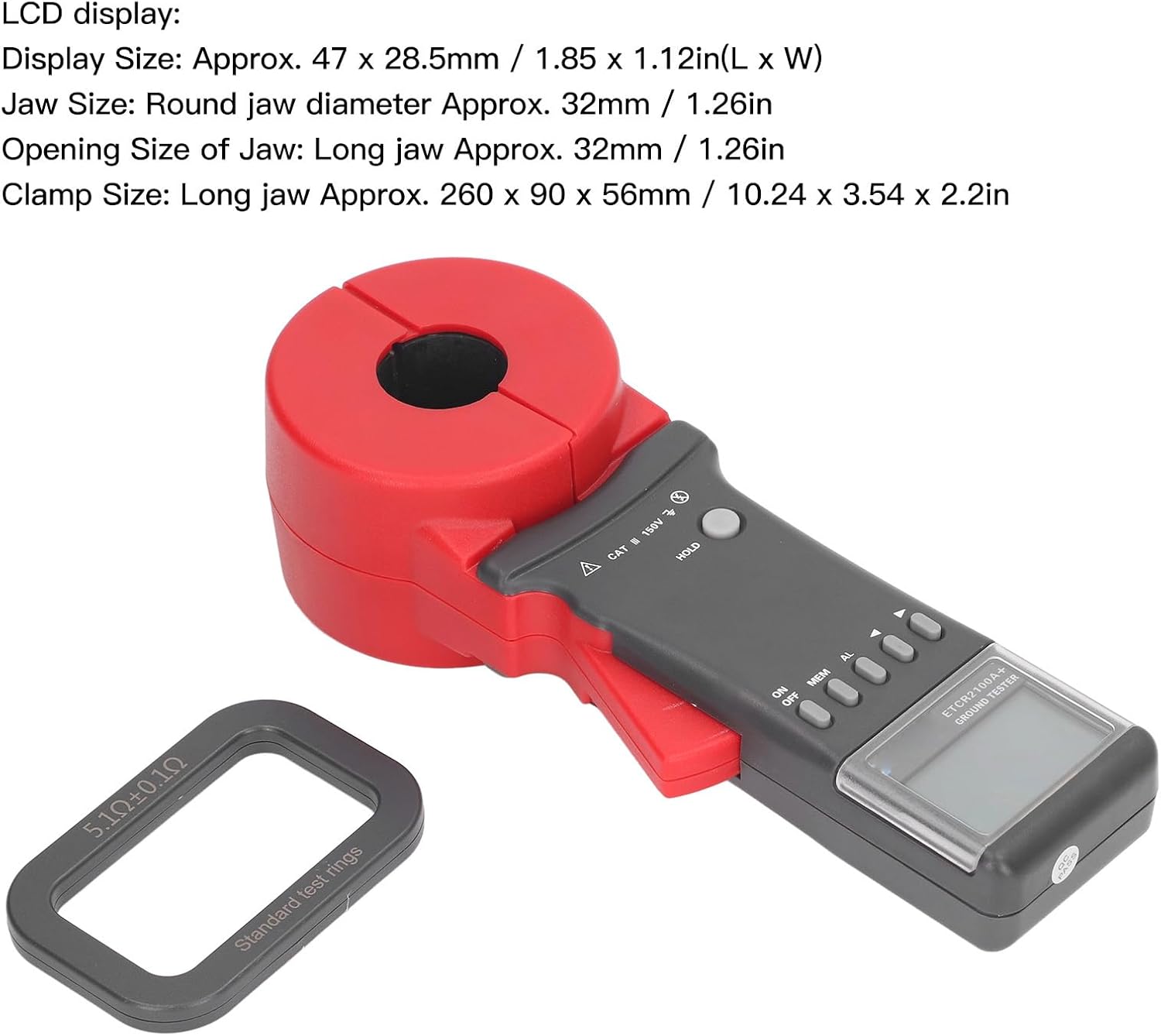
Image 1.1: The Tyenaza ETCR2100A+ Digital Clamp Resistance Tester, showing its overall design with the clamp jaw and control panel.
2. Sicherheitshinweise
Always observe the following safety precautions to avoid electric shock, injury, or damage to the instrument:
- Das Gerät darf nicht verwendet werden, wenn es beschädigt erscheint oder nicht ordnungsgemäß funktioniert.
- Vor dem Betrieb sicherstellen, dass das Batteriefach fest verschlossen ist.
- Versuchen Sie nicht, an stromführenden Leitungen die angegebene Spannung zu überschreiten.tage limits (CAT III 150V).
- Avoid using the instrument in wet environments or during thunderstorms.
- Refer to qualified personnel for any repairs or servicing.
- Keep the instrument away from strong magnetic fields and electric fields exceeding specified limits.
3. Packungsinhalt
Überprüfen Sie, ob alle Artikel im Paket vorhanden sind:
- 1 x ETCR2100A+ Digital Clamp Widerstandstester
- 1 x Accessory (likely a test ring or similar calibration aid)
- 1 x Benutzerhandbuch (dieses Dokument)
- 1 x Aufbewahrungsbox
Note: 1.5V AA batteries (x4) are required and are not included in the package.

Image 3.1: The ETCR2100A+ tester shown with a standard test ring, which is typically included as an accessory for calibration or verification.
4. Produktmerkmale
Der digitale Cl ETCR2100A+amp Resistance Tester offers the following key features:
- Multifunktionsdisplay: Resistance and current values are displayed simultaneously on a new black luxury screen.
- Hohe Genauigkeit: Microprocessor-controlled for precise grounding resistance detection, utilizing fast filtering technology to minimize interference.
- Datenverwaltung: Features real-time clock, data storage for up to 99 sets, and data retrieval capabilities.
- Akustischer und optischer Alarm: "Beep beep beep" alarm sound with adjustable threshold settings for resistance (1-199 Ω) and current (1-499mA).
- Automatische Funktionen: Automatic shutdown and fully automatic gear shifting for ease of use.
- Robustes Design: Shockproof and dustproof structure, suitable for demanding industrial environments.
- Breite Anwendung: Ideal for telecommunications, power, meteorology, computer rooms, oil fields, power distribution lines, tower transmission lines, gas stations, factory grounding grids, and lightning rod systems.

Bild 4.1: Eine Nahaufnahme view of the robust clamp jaws, highlighting the double insulation and structural features designed for durability and safety.
5. Einrichtung
5.1 Einlegen der Batterie
The ETCR2100A+ requires four (4) 1.5V AA batteries (not included).
- Suchen Sie den Batteriefachdeckel auf der Rückseite des Instruments.
- Use a suitable tool (if necessary) to open the battery compartment.
- Insert four 1.5V AA batteries, ensuring correct polarity (+/-) as indicated inside the compartment.
- Schließen Sie den Batteriefachdeckel fest.
5.2 Erstes Einschalten
Nach dem Einlegen der Batterie drücken Sie die EIN/AUS button to power on the device. The LCD display will illuminate, indicating the device is ready for use.
6. Bedienungsanleitung
6.1 Grundlegende Messung
To perform a grounding resistance test:
- Stellen Sie sicher, dass das Instrument eingeschaltet ist.
- Öffne dieamp Die Kiefer werden durch Drücken des Auslösers geöffnet.
- Platzieren Sie dieamp around the grounding conductor or circuit to be measured. Ensure the jaws are fully closed around the conductor.
- The resistance value will be displayed on the LCD screen. The device features fully automatic shifting.
- The single measurement time is approximately 0.5 seconds.
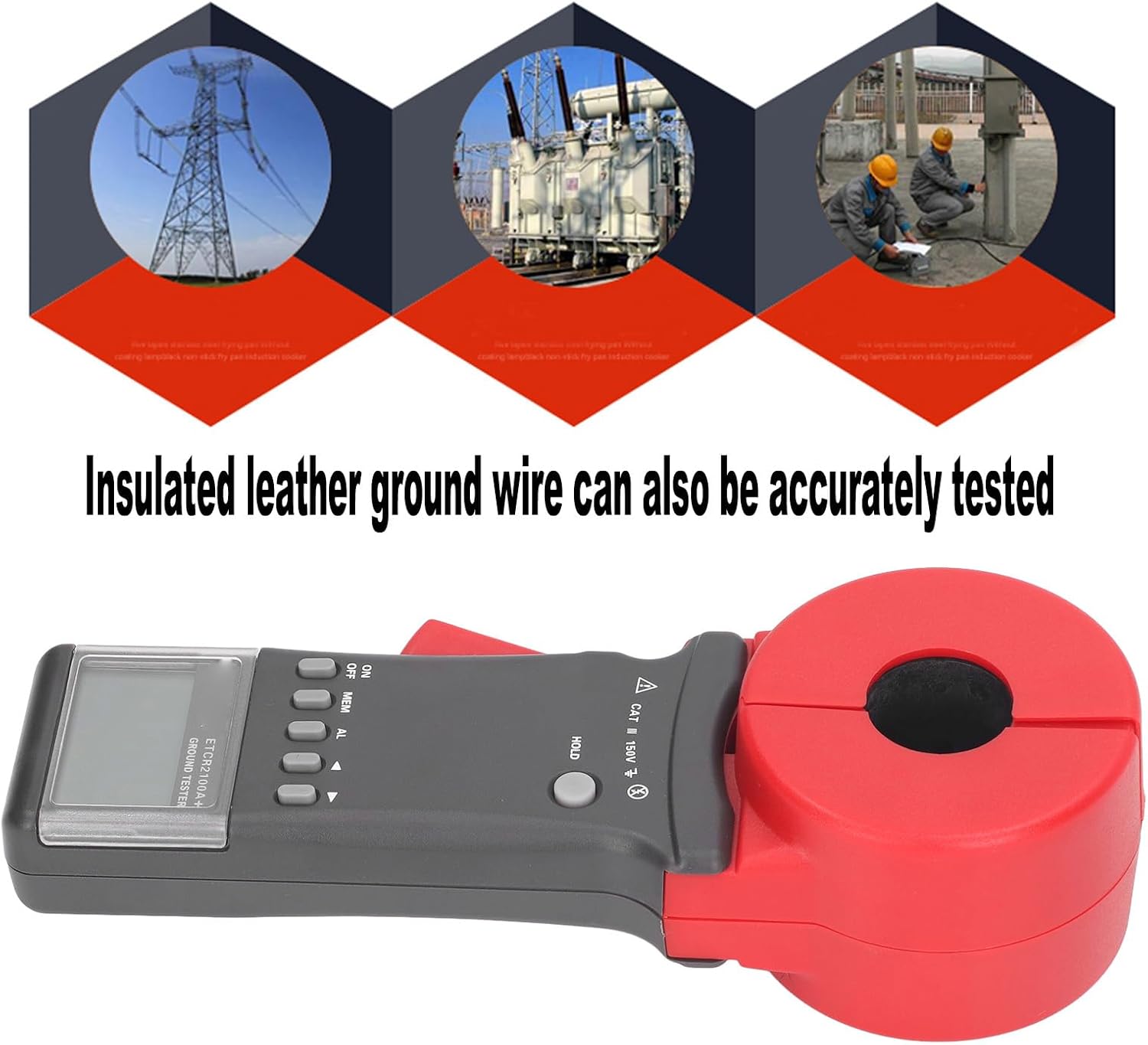
Image 6.1: The ETCR2100A+ tester shown clamping an insulated ground wire, demonstrating its capability to accurately test even insulated conductors.
6.2 Single Point Grounding System, Auxiliary Measurement
For single point grounding systems where direct clamp measurement of the lead wire is not feasible, auxiliary methods can be used. The two-point method is illustrated below:

Image 6.2: Diagram showing the two-point method for auxiliary grounding resistance measurement. It depicts a grounding rod (RA) connected to a single point, with a wire extending to a natural grounding point (e.g., water pipe, buried metal) for measurement.
So verwenden Sie diese Methode:
- Identify a natural grounding point with a low resistance value near the grounding point to be measured. Examples include a water pipe, fire hydrant, or other deeply buried metal structure.
- Connect a wire from the point to be measured to this auxiliary grounding point.
- Clamp the ETCR2100A+ around the connecting wire to perform the measurement.
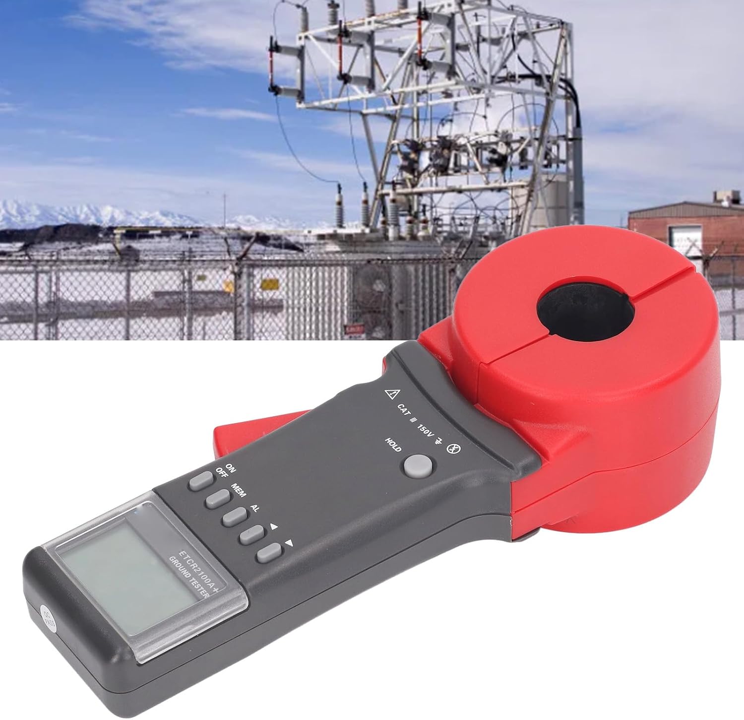
Image 6.3: The ETCR2100A+ tester positioned in an industrial substation, illustrating a typical application environment for grounding resistance measurement.
6.3 Datenspeicherung und -abruf
Das Gerät kann bis zu 99 Messdatensätze speichern.
- To store data: After a measurement, press the MEM button to save the current reading.
- To retrieve data: Press the MEM button repeatedly to cycle through stored data.
6.4 Alarmfunktion
The ETCR2100A+ features an audible and visual alarm for out-of-range measurements.
- To activate/deactivate the alarm: Press the AL Taste.
- To set alarm thresholds: Refer to the device's on-screen menu or specific instructions for setting resistance (1-199 Ω) and current (1-499mA) alarm limits.

Image 6.4: A hand holding the ETCR2100A+ tester, demonstrating its ergonomic design and ease of handling during operation.
7. Wartung
7.1 Reinigung
Wipe the instrument's exterior with a soft, damp Mit einem Tuch abwischen. Keine Scheuermittel oder Lösungsmittel verwenden. Vor der Reinigung sicherstellen, dass das Gerät ausgeschaltet ist.
7.2 Speicherung
When not in use for extended periods, remove the batteries to prevent leakage. Store the instrument in its provided storage box in a cool, dry place, away from direct sunlight and extreme temperatures.
7.3 Kalibrierung
Regular calibration by qualified personnel is recommended to maintain measurement accuracy, especially after prolonged use or if accuracy is suspected to be compromised.
8. Fehlerbehebung
| Problem | Mögliche Ursache | Lösung |
|---|---|---|
| Gerät lässt sich nicht einschalten. | Defekte oder falsch eingesetzte Batterien. | Ersetzen Sie die Batterien durch neue 1.5V AA-Batterien und achten Sie dabei auf die richtige Polarität. |
| Ungenaue Messwerte. | Jaws not fully closed; interference from external fields; dirty jaws; need for calibration. | Ensure jaws are fully closed. Move away from strong magnetic/electric fields. Clean jaws. Consider professional calibration. |
| Der Alarm ertönt kontinuierlich. | Measurement exceeds set alarm threshold. | Check the measured value against the set alarm limits. Press the AL button to silence or deactivate the alarm. |
| Der Bildschirm ist leer oder flackert. | Low battery power; environmental conditions (extreme temperature/humidity). | Replace batteries. Operate within specified temperature and humidity ranges (-20 ℃ to 55 ℃; 10% RH to 90% RH). |
9. Spezifikationen
| Modell | ETCR2100A+ |
| Funktion | Grounding resistance test, circuit resistance test, leakage current test |
| Widerstandsbereich | 0.01 Ω bis 200 Ω |
| Widerstandsauflösung | 0.001 Ω |
| Aktueller Bereich | None (for leakage current test, the range is 1-499mA for alarm setting) |
| Datenspeicherung | 99 Sätze |
| Alarm Threshold Setting Range (Resistance) | 1-199 Ω |
| Alarm Threshold Setting Range (Current) | 1-499 mA |
| Arbeitstemperatur und Luftfeuchtigkeit | -20 ℃ to 55 ℃; 10% RH to 90% RH |
| LCD Anzeige | 4 digit LCD digital display |
| Anzeigegröße | Approx. 47 x 28.5mm / 1.85 x 1.12in (L x W) |
| Jaw Size (Round) | Approx. 32mm / 1.26in diameter |
| Jaw Opening Size (Long) | Ca. 32 mm / 1.26 Zoll |
| Clamp Size (Long Jaw) | Ca. 260 x 90 x 56 mm / 10.24 x 3.54 x 2.2 Zoll |
| Schutzstufe | Doppelte Isolierung |
| Strukturelle Merkmale | Clamp shaped CT |
| Gangwechsel | Fully automatic shifting |
| Externes Magnetfeld | <40 A / m |
| Externes elektrisches Feld | <1 V / m |
| Einzelmesszeit | 0.5 Sekunden |
| Resistance Measurement Frequency | Greater than 1KHz |
| Tested Current Frequency | 50/60Hz automatic |
| Stromversorgung | 4 x 1.5 V AA-Batterien (nicht im Lieferumfang enthalten) |
| Material | ABS |
| Artikelgewicht | 2.13 Kilogramm / 4.69 Pfund |
10. Garantie und Support
Informationen zu Garantie, technischem Support oder Serviceanfragen erhalten Sie bei Ihrem Händler oder direkt beim Hersteller. Bewahren Sie Ihren Kaufbeleg als Kaufnachweis auf.
Manufacturer: Tyenaza
Ask a question about this manual
Ask about setup, troubleshooting, compatibility, parts, safety, or missing instructions. Manuals+ will review the question and use this page’s manual context to help answer it.