FLIPSKY 14S150A
FLIPSKY 14S 150A LiFePO4/Li-Ionen-Batteriemanagementsystem (BMS) – Benutzerhandbuch
Modell: 14S150A
1. Einleitung
This manual provides essential instructions for the safe and effective use of the FLIPSKY 14S 150A Battery Management System (BMS). This BMS is designed to protect LiFePO4 and Li-ion battery packs, commonly used in applications such as ESK8 and electric scooters, by monitoring and managing various battery parameters.
Please read this manual thoroughly before installation and operation to ensure proper functionality and to prevent damage to the BMS or battery pack.
2. Sicherheitshinweise
Adherence to safety guidelines is critical when working with battery management systems and high-power battery packs. Failure to follow these instructions can result in serious injury, fire, or damage to equipment.
- Always ensure correct wiring polarity. Incorrect connections can cause immediate damage to the BMS and battery.
- Die Batteriepole oder den BMS-Ausgang dürfen nicht kurzgeschlossen werden.
- Handle the BMS and battery pack with care to avoid physical damage.
- Sorgen Sie während des Lade- und Entladevorgangs für ausreichende Belüftung.
- Operating temperature range: -30°C to +80°C. Avoid operating outside this range.
- Working power consumption: <35µA. Over-discharge power consumption (Sleeping State): <10µA.
- If any abnormal behavior is observed, immediately disconnect the battery pack from the load and charger.
3. Produktmerkmale
The FLIPSKY 14S 150A BMS offers comprehensive protection and management for your battery pack:
- Überladeschutz: Verhindert, dass Zellen über ihre sichere Ladespannung hinaus geladen werden.tage Grenze.
- Überentladungsschutz: Protects cells from being discharged below their safe voltage Grenze.
- Überstromschutz: Safeguards against excessive discharge currents.
- Balanced Protection: Gleicht aktiv das Zellvolumen aus.tages during charging to prolong battery life.
- Temperaturkontrollschutz: Monitors battery temperature and prevents operation outside safe thermal limits.
- Applicable for 8-14S battery configurations.

Figure 1: Key Features of the FLIPSKY 14S 150A BMS.
4. Spezifikationen

Figure 2: FLIPSKY 14S 150A BMS Overview.
| Parameter | Wert |
|---|---|
| Ladestrom | <60 A |
| Entladestrom | <150 A |
| Innenwiderstand | ≤15mΩ |
| Ladevolumentage | (Number of Li-ion cells in series) x 4.2V |
| Verdrahtungstyp | Different Port (Separate charge/discharge) |
| Überladeerkennung Voltage | 4.25 ± 0.025 V |
| Überladefreigabe Voltage | 4.15 ± 0.05 V |
| Überentladungserkennung Voltage | 2.75 ± 0.1 V |
| Over-discharge Release Voltage | 3.0 ± 0.1 V |
| Balance Detection Voltage | 4.15 ± 0.025 V |
| Saldo aktuell | 42 ± 5MA |
| Überentladestromschutz | 300±50A, 450±50A, 600±60A (Configurable) |
| Kurzschlussschutzverzögerung | 300µs |
| Charge/Discharge Over-temperature Protection | 55°C |
| Charge/Discharge High Temperature Release | 75°C |
| Betriebstemperaturbereich | -30°C bis +80°C |
| Abmessungen (L*B*H) | 121mm * 50mm * 12.8mm (4.76 x 1.97 x 0.5 inches) |
| Nettogewicht | 244 g |

Figure 3: BMS Dimensions.

Abbildung 4: Detaillierte technische Spezifikationen.
5. Einrichtung und Installation
Careful installation is crucial for the proper functioning and safety of the BMS. Follow these steps precisely:
- Initial Connection Precaution: It is strictly forbidden to insert the balance wires into the BMS before connecting the main battery terminals (B-). Ensure the main negative battery cable (B-) is securely connected first.
- Balance Wire Soldering: Make sure all balance cables are correctly soldered to their respective battery cell positive terminals.
- Sequence of Connecting Balance Wires:
- Start from the thin black balance wire (B0 or B-) which connects to the main negative terminal of the battery pack.
- Connect the second wire (thin red wire, B1) to the positive terminal of the first battery cell.
- Continue connecting each subsequent balance wire to the positive terminal of the next cell in series, in ascending order (B2, B3, ..., B14), until the last positive terminal (B+) of the battery pack is connected.
- Bandtage Verification (Crucial Step): Do not insert the balance plug directly after connecting the cables. First, measure the voltage between each two adjacent metal terminals on the back of the balance plug.
- For ternary polymer batteries, the voltage between adjacent terminals should be between 3.0V and 4.2V.
- For iron-lithium (LiFePO4) batteries, the voltage sollte zwischen 2.0V und 3.6V liegen.
- Die voltage between adjacent terminals should be approximately 1.5V to 2.75V for other cell types, depending on their nominal voltage.
- Balance Plug Insertion: After confirming that the wiring sequence and voltages of all balance cables are correct, carefully insert the balance plug into the corresponding socket on the protection board.
Attention: Cables from different manufacturers are not universally compatible. Always use the matching cables provided with your BMS or verified compatible replacements.
- Letzter Bandtage Überprüfen Sie: After the wiring is completed, measure the voltage between battery B+ and B-, and the voltage between B- and C-. If these voltages are equal, the protection board is working normally and can be used. If they are not equal, recheck all wiring connections.

Figure 5: 14S BMS Wiring Diagram (Different Port).
6. Bedienung
Once correctly installed, the BMS operates automatically to protect your battery pack. It continuously monitors cell voltagStrömungen, Strömungen und Temperaturen.
- Laden: Connect your charger to the C+ and C- terminals. The BMS will manage the charging process, including cell balancing and overcharge protection.
- Entladen: Connect your load (e.g., ESK8 motor, electric scooter motor) to the P+ and P- terminals. The BMS will monitor discharge current and cell voltages to prevent over-discharge and overcurrent conditions.
- Schutzaktivierung: If any parameter exceeds its safe limit (e.g., overcharge, over-discharge, overcurrent, over-temperature), the BMS will temporarily disconnect the battery from the charger or load to prevent damage. It will automatically resume operation once conditions return to safe levels.
7. Wartung
The FLIPSKY BMS is designed for minimal maintenance. However, periodic checks can help ensure its longevity and reliable performance:
- Sichtprüfung: Überprüfen Sie das BMS und die gesamte Verkabelung regelmäßig auf Anzeichen von Beschädigungen, Korrosion oder losen Verbindungen.
- Sauberkeit: Keep the BMS free from dust, dirt, and moisture. Use a dry, soft cloth for cleaning.
- Temperaturmanagement: Ensure the BMS and battery pack are operated within their specified temperature ranges. Good airflow around the unit is beneficial, especially during high current draw. The aluminum alloy shell aids in heat dissipation.
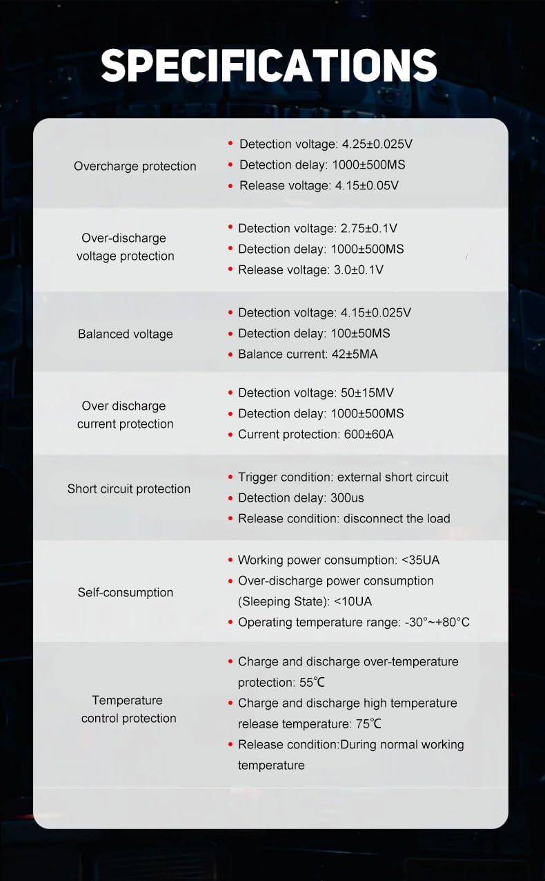
Abbildung 6: Gehäuse aus Aluminiumlegierung zur Wärmeableitung.
8. Fehlerbehebung
If you encounter issues with your BMS or battery pack, consider the following troubleshooting steps:
- Keine Leistungsabgabe:
- Check all main power connections (B-, P-, C-) for secure contact and correct polarity.
- Verify the balance wire connections are correct and the plug is fully seated.
- Measure individual cell voltages. If any cell is significantly out of balance or below its minimum voltage, the BMS may have activated under-voltage Schutz.
- Check for short circuits in the load or wiring.
- Ladeprobleme:
- Ensure the charger is functioning correctly and provides the correct voltage.
- Verify the C+ and C- connections.
- Check for overcharge protection activation if cells are already full.
- BMS-Überhitzung:
- Reduce the load current if possible.
- Sorgen Sie für ausreichende Belüftung rund um das Gebäudeleitsystem.
- Verify that the BMS is rated for your application's continuous and peak current draw.
- Unausgewogene Zellen:
- Stellen Sie sicher, dass alle Balancerleitungen korrekt angeschlossen sind und einen guten Kontakt haben.
- Allow the battery pack to sit connected to the BMS for an extended period (e.g., overnight) to allow passive balancing to occur.
If problems persist after troubleshooting, contact FLIPSKY customer support for further assistance.
9. Packungsinhalt
The package for the FLIPSKY 14S 150A BMS typically includes:
- 1x PCBA board (FLIPSKY 14S 150A BMS)
- 1x HY2.0 single head 15P line (Balance cable)

Abbildung 7: Packungsinhalt.
Ask a question about this manual
Ask about setup, troubleshooting, compatibility, parts, safety, or missing instructions. Manuals+ will review the question and use this page’s manual context to help answer it.