
1. Einleitung
This manual provides essential information for the safe and effective operation of your Mastech MY70 Digital Multimeter. Please read this manual thoroughly before use and retain it for future reference. The Mastech MY70 is a compact, battery-powered digital multimeter designed for measuring AC/DC voltage, AC/DC current, resistance, diode, and transistor hFE. It is suitable for domestic, industrial, and electronics applications.
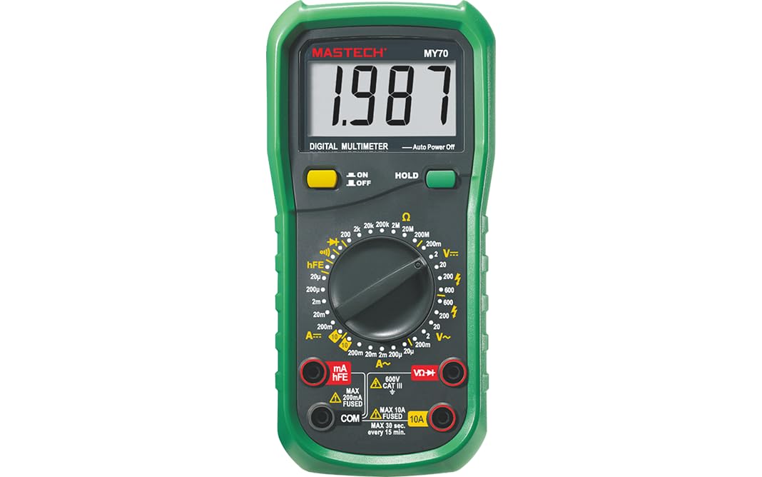
Abbildung 1: Vorderseite view of the Mastech MY70 Digital Multimeter.
2. Sicherheitshinweise
WARNING: To avoid electric shock or personal injury, and to avoid damage to the meter or to the equipment under test, follow these safety rules:
- Nicht mehr als die angegebene Menge auftragen.tage) wie auf dem Messgerät markiert, zwischen den Klemmen oder zwischen einer beliebigen Klemme und der Erdung.
- Seien Sie vorsichtig beim Arbeiten mit VolumentagSpannungen über 30 V AC RMS, 42 V Spitze oder 60 V DC. Solche SpannungentagEs besteht die Gefahr eines Stromschlags.
- Vor dem Ändern von Funktionen oder Messbereichen müssen die Messleitungen immer vom Stromkreis getrennt werden.
- Stellen Sie sicher, dass die Messleitungen in gutem Zustand sind und keine Beschädigungen an der Isolierung aufweisen.
- Verwenden Sie das Messgerät nicht, wenn es beschädigt erscheint oder das Gehäuse geöffnet ist.
- Verwenden Sie für Ihre Messungen stets die richtigen Anschlüsse, Funktionen und Messbereiche.
- Tauschen Sie die Batterie aus, sobald die Anzeige für niedrigen Batteriestand erscheint, um genaue Messwerte zu gewährleisten.
3. Packungsinhalt
Bitte überprüfen Sie, ob alle unten aufgeführten Artikel in Ihrem Paket enthalten sind:
- Mastech MY70 Digital Multimeter (approx. 188x93x50mm, 380g/0.84lb)
- Messleitungen (eine rote, eine schwarze)
- Multi-function Socket
- 1 x 9V 6F22 Batterie
- Kalibrierzertifikat
- Kurzanleitung

Figure 2: Mastech MY70 Multimeter, test leads, multi-function socket, battery, and documentation. This image also illustrates the main applications of the multimeter in domestic, industrial, and electronics settings.
4. Einrichtung
4.1 Einlegen der Batterie
- Stellen Sie sicher, dass das Multimeter ausgeschaltet und die Messleitungen abgeklemmt sind.
- Suchen Sie die Abdeckung des Batteriefachs auf der Rückseite des Multimeters.
- Die Befestigungsschraube(n) lösen und die Abdeckung abnehmen.
- Insert the 9V 6F22 battery, observing the correct polarity (+ and -).
- Bringen Sie die Abdeckung des Batteriefachs wieder an und befestigen Sie sie mit der/den Schraube(n).
4.2 Anschließen der Testleitungen
- Für die meisten Messungen (Vol.tage, resistance, continuity, diode, hFE), insert the black test lead into the "COM" (common) jack.
- Stecken Sie die rote Messleitung in die Buchse „VΩmA“.
- For current measurements exceeding 200mA (up to 10A), insert the red test lead into the "10A" jack.
5. Bedienungsanleitung
The Mastech MY70 features a rotary switch for function selection and a digital display for readings.
5.1 Funktionsauswahl
Turn the rotary switch to the desired measurement function (e.g., DCV, ACV, DCA, ACA, Ω, Diode, hFE). The meter will automatically select the appropriate range for most measurements (auto-ranging), or you may need to manually select a range depending on the model variant.
5.2 Messungen durchführen
- DC-Voltage (DCV): Select the DCV function. Connect the test leads in parallel with the DC voltagDie Quelle.
- AC-Lautstärketage (ACV): Select the ACV function. Connect the test leads in parallel with the AC voltagDie Quelle.
- Gleichstrom (DCA): Select the DCA function. Connect the meter in series with the circuit. Ensure the red lead is in the correct current jack (mA or 10A).
- Wechselstrom (ACA): Select the ACA function. Connect the meter in series with the circuit. Ensure the red lead is in the correct current jack (mA or 10A).
- Widerstand (Ω): Select the Ω function. Ensure the circuit is de-energized. Connect the test leads across the component to measure resistance.
- Diodentest: Select the Diode function. Connect the red lead to the anode and the black lead to the cathode of the diode. The forward voltagDer Drop wird angezeigt.
- Durchgangsprüfung: Select the Continuity function. Connect the test leads across the circuit or component. A buzzer will sound if continuity is detected (resistance less than 50Ω).
- Transistor-hFE-Test: Insert the transistor into the multi-function socket, ensuring correct pin orientation (EBC for NPN or PNP). Select the hFE function. The hFE value will be displayed.
5.3 Sonderfunktionen
- Datenaufnahme: Drücken Sie die Taste „HOLD“, um den aktuellen Messwert auf dem Display einzufrieren. Drücken Sie erneut, um die Taste zu lösen.
- Automatisches Ausschalten: Das Messgerät schaltet sich nach einer gewissen Zeit der Inaktivität automatisch ab, um die Batterielebensdauer zu verlängern.
- Anzeige für niedrigen Batteriestand: Ein Symbol erscheint auf dem Display, wenn der Akkustand niedrig ist.tage is low, indicating that the battery needs replacement.
6. Wartung
6.1 Batteriewechsel
When the low battery indicator appears on the display, replace the 9V 6F22 battery as described in Section 4.1. Using a low battery can lead to inaccurate readings.
6.2 Reinigung
Löschen Sie den Fall mit Anzeigeamp Mit einem Tuch und mildem Reinigungsmittel reinigen. Keine Scheuermittel oder Lösungsmittel verwenden. Die Anschlüsse sauber und trocken halten.
6.3 Speicherung
If the meter is not to be used for an extended period, remove the battery to prevent leakage and damage to the meter.
7. Fehlerbehebung
- Keine oder nur schwache Anzeige: Überprüfen Sie den Batterieeinbau und tauschen Sie ihn gegebenenfalls aus.
- Falsche Messwerte: Ensure correct function and range selection. Check test lead connections and condition. Verify battery level.
- Anzeige: „OL“ (Überlastung): Der Messwert liegt außerhalb des gewählten Bereichs. Wählen Sie gegebenenfalls einen höheren Messbereich oder eine andere Funktion.
- Kein Kontinuitätssignal: Check if the resistance is above 50Ω. Ensure test leads are properly connected.
8. Spezifikationen
The following table details the technical specifications of the Mastech MY70 Digital Multimeter:

Figure 3: Detailed specifications for the Mastech MY70, including ranges, resolutions, and accuracies for various measurement functions.
| Parameter | Wert |
|---|---|
| Anzeige | 2000 Zählwerte |
| Automatische Abschaltung | Ja |
| Daten halten | Ja |
| Niedrige Batterieanzeige | Ja |
| Transistor hFE | 0 bis 1000 |
| Diode Open Voltage | 3.0 V |
| Durchgangssummer | <50Ω |
| Hersteller | MASTECH |
| Modellnummer | YQ-MY70 |
| Artikelgewicht | 1 kg |
| Technische Daten | 20 x 15 x 25 cm |
| Batterien | 2 LR44 batteries (included) - Note: Package contents list 1x9V 6F22 battery. Please verify upon receipt. |
| Material | Acrylnitril-Butadien-Styrol |
| Stromquellentyp | Batteriebetrieben |
| Messgenauigkeit | 0.4 % (typisch) |
| Zertifizierungen | CE, RoHS, UL |
| Ursprungsland | Taiwan |
| Obere Temperaturbewertung | 50 Grad Celsius |
For a comparison of features across different Mastech digital multimeters, refer to the following table:

Figure 4: Feature comparison table for various Mastech digital multimeters, including the MY70 model.
9. Garantie und Support
For information regarding warranty coverage, technical support, or service, please refer to the official Mastech webBesuchen Sie unsere Website oder kontaktieren Sie Ihren Händler vor Ort. Bewahren Sie Ihren Kaufbeleg als Kaufnachweis auf.