
1. Einleitung
This manual provides detailed instructions for the safe and effective operation of your WLLKIY ET31C/ET32C Automotive Signal Generator Multimeter. This device combines the functions of a signal generator and a multimeter, designed for automotive diagnostics and testing. It can simulate various automotive sensor signals, test ignition coils, and perform standard multimeter measurements.

Figure 1: WLLKIY ET31C/ET32C Automotive Signal Generator Multimeter and included accessories.
2. Sicherheitshinweise
Bitte lesen und verstehen Sie alle Sicherheitshinweise und Bedienungsanweisungen, bevor Sie dieses Gerät verwenden. Die Nichtbeachtung dieser Anweisungen kann zu Stromschlag, Brand oder schweren Verletzungen führen.
- Always wear appropriate personal protective equipment, such as safety glasses, when working on vehicles.
- Verwenden Sie das Gerät nicht, wenn es beschädigt erscheint oder die Messleitungen beschädigt sind.
- Ensure the device is powered off before connecting or disconnecting test leads.
- Vermeiden Sie den Kontakt mit stromführenden Stromkreisen.
- Do not exceed the maximum input ratings specified in the specifications section.
- Das Gerät sollte vor Feuchtigkeit und extremen Temperaturen geschützt werden.
3. Packungsinhalt
Bitte überprüfen Sie, ob alle unten aufgeführten Artikel in Ihrem Paket enthalten sind:
- 1 x Signal Generator Multimeter (ET31C or ET32C model)
- 1 x Paar Messleitungen
- 1 x Pair of Alligator Clip Wires
- 1 x USB Type-C Cable (for ET32C charging, or data for both)
- 1 x englisches Benutzerhandbuch
Note: For ET31C, 3x 1.5V AAA batteries are required and are not included. The ET32C model includes a built-in 4.2V lithium battery.
4. Einrichtung
4.1 Einschalten des Geräts
- For ET31C: Open the battery compartment on the back of the device. Insert 3x 1.5V AAA batteries, ensuring correct polarity. Close the compartment.
- For ET32C: The device has a built-in rechargeable battery. If the battery is low, connect the included USB Type-C cable to the device and a suitable USB power source (e.g., computer USB port, USB wall adapter).
- Zum Einschalten des Geräts den Netzschalter (normalerweise mit einem Netzschaltersymbol gekennzeichnet) gedrückt halten.
4.2 Anschließen der Testleitungen
Connect the test leads or alligator clip wires to the appropriate input jacks on the bottom of the device.
- COM-Buchse: Common (negative) input for all measurements and signal output.
- VΩHz-Buchse: Positiver Input für Voltage, Widerstands-, Frequenz-, Kapazitäts-, Dioden- und Durchgangsmessungen.
- Ausgangsbuchse: Positive output for signal generation.
5. Bedienungsanleitung
5.1 Umschalten zwischen den Betriebsmodi
The device operates in two primary modes: Signal Generator and Multimeter. Use the MODUS button to switch between these functions. The current mode will be displayed on the 2.8-inch screen.
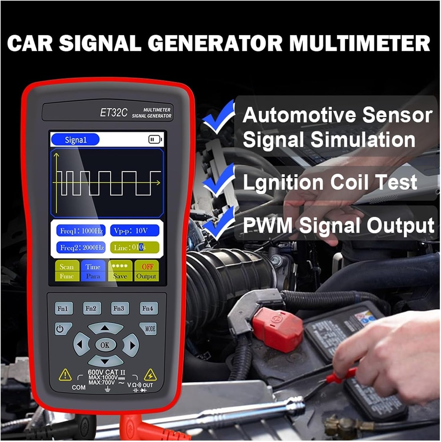
Figure 2: The device in use for automotive sensor signal simulation and ignition coil testing.
5.2 Funktionen des Signalgenerators
This mode allows you to generate various electrical signals for testing automotive components.
- Signaltypen: Sine wave, Square wave, Combined wave (e.g., 58+2, 10+1 missing teeth), Scan wave, and DC wave.
- Frequenzbereich: 1Hz to 9999Hz (adjustable in 1Hz steps).
- Ausgangsvolumentage (Spitze-Spitze): -12V to +12V (adjustable in 1V steps).
- Duty Cycle (for Square Wave): 1 % bis 99 %.
- Scan Wave: Simulates crankshaft/camshaft signal changes from low to high speed (scan time 1s to 999s).
- Combined Wave: Allows setting of missing teeth signals (e.g., 58+2, 10+1). Maximum combined wave combinations: 99+99.
- Wellenformspeicherung: The instrument supports storing up to 50 sets of waveform parameters.

Figure 3: Display illustrating combined wave signal generation with missing teeth settings.

Figure 4: The device's waveform storage feature, allowing up to 50 sets of parameters to be saved.
5.2.1 Automotive Signal Simulation
The signal generator can simulate Hall-type and magneto-electric crankshaft and camshaft signals. This is useful for diagnosing engine management systems without needing to run the engine.
- Supports simulation for both gasoline and diesel vehicles.
- Simulate various sensor outputs to test ECU responses.

Figure 5: The device functioning as a vehicle maintenance signal source, simulating sensor outputs.
5.2.2 Ignition Coil Control
The device can control ignition coils, solenoid valves, and relays to test their functionality.
- Coil control power: Less than 30V/1A.
- Connect the output to the component to be tested and observe its operation.

Figure 6: Screen showing the ignition coil test function, used to verify normal operation of coils, solenoid valves, and relays.
5.3 Multimeterfunktionen
In multimeter mode, the device performs standard electrical measurements.
- DC-Voltage: Max 1000V.
- AC-Lautstärketage: Max 750V.
- Widerstand: Max 40MΩ.
- Kapazität: Max 100uF.
- Frequenz: Max 50KHz.
- Arbeitszyklus: 0.1 % bis 99.9 %.
- Diodentest: 0V bis 1.5V.
- Durchgangsprüfung: Resistance value for continuity detection: Max 30Ω.
- Anzeige: 4000 counts, updates 3 times per second.

Figure 7: The device's multimeter display showing a measurement, alongside details of the 2.8-inch screen with 320x480 resolution.
6. Spezifikationen
6.1 Allgemeine Spezifikationen
- Anzeige: 2.8-inch, 320 * 480 resolution
- Touch-Screen: Nicht unterstützt
- USB-Schnittstelle: Typ-C USB
- Battery (ET31C): 3 x 1.5V AAA-Batterien (nicht im Lieferumfang enthalten)
- Battery (ET32C): Eingebaute 4.2-V-Lithiumbatterie
- Lagertemperatur: -20 °C bis 60 °C (-4 °F bis 140 °F)
- Betriebstemperatur: 0 °C bis 50 °C (32 °F bis 122 °F)
- Luftfeuchtigkeit: <85% rF (nicht kondensierend)
- Produktabmessungen (LxBxH): 134 mm * 69 mm * 25 mm
- Produktgewicht: 125 g (excluding accessories)
6.2 Signalgeneratorparameter
- Sine Wave/Square Wave Frequency Range: 1Hz ~ 9999Hz
- Sine Wave/Square Wave Frequency Step: 1 Hz
- Sine Wave/Square Wave Peak Range: -12 V bis +12 V
- Sine Wave/Square Wave Peak Step: 1V
- Scan Wave Scan Time Range: 1 s bis 999 s
- Maximum Combined Wave Combinations: 99+99
- Ausgangsvolumentage Reichweite: -12 V bis +12 V
- Ausgangsvolumentage Schritt: 1V
- Coil Control Power: Less than 30V/1A
- Wellenformspeicherung: 50 Sätze
- Duty Setting (for Square Wave only): 1 % bis 99 %
6.3 Multimeterparameter
- Maximale DC-Eingangsspannungtage: 1000 V
- Maximale AC-Eingangsspannungtage: 750 V
- Maximum Measured Resistance: 40 MΩ
- Maximum Measured Capacitance: 100uF
- Maximum Frequency Measurement: 50 KHz
- Duty Cycle Measurement Range: 0.1 % bis 99.9 %
- Diode Measurement Range: 0V ~ 1.5V
- Maximum Resistance for Continuity Detection: 30 Ω
- Anzeigezähler: 4000 Zählwerte
- Aktualisierungsrate: 3 mal pro Sekunde
7. Wartung
- Reinigung: Wischen Sie das Gerät mit einem weichen, damp Tuch. Keine Scheuer- oder Lösungsmittel verwenden.
- Lagerung: Store the device in a cool, dry place away from direct sunlight and extreme temperatures. If storing for extended periods, remove AAA batteries from the ET31C model.
- Battery Care (ET32C): For optimal battery life, avoid fully discharging the battery frequently. Charge the device regularly if not in use for long periods.
- Messleitungen: Prüfen Sie die Messleitungen vor jedem Gebrauch auf Beschädigungen (Schnitte, Risse). Beschädigte Leitungen müssen umgehend ausgetauscht werden.
8. Fehlerbehebung
| Problem | Mögliche Ursache | Lösung |
|---|---|---|
| Gerät lässt sich nicht einschalten. |
|
|
| Incorrect readings in Multimeter mode. |
|
|
| No signal output from Signal Generator. |
|
|
9. Garantie und Support
For warranty information and technical support, please refer to the documentation provided with your purchase or contact WLLKIY customer service directly. Contact details can typically be found on the manufacturer's official webauf der Website oder auf der Produktverpackung.