
Walfront KDT2400B 007
Walfront RF Power Amplifier-Benutzerhandbuch
Model: KDT2400B 007
1. Einleitung
This user manual provides detailed instructions for the Walfront RF Power Amplifier, Model KDT2400B 007. This compact and efficient amplifier is designed for various RF applications, offering reliable performance across a broad frequency range. Please read this manual thoroughly before operating the device to ensure proper use and longevity.
2. Sicherheitshinweise
- Lastanschluss: Always connect a proper 50 Ω load to the output before powering on the device. Operating without a load can severely damage the ampschwerer.
- Wärmeableitung: The module generates heat during operation. Ensure adequate ventilation and do not obstruct the heatsink. Prolonged operation may require additional cooling.
- Stromversorgung: Use a stable 6V DC power supply with sufficient current capacity (450mA at maximum output). Incorrect voltage or unstable power can lead to malfunction or damage.
- Handhabung: Behandeln Sie das Gerät mit Sorgfalt. Vermeiden Sie es, es fallen zu lassen oder starken Stößen auszusetzen.
- Umfeld: Setzen Sie die amplifier to moisture, extreme temperatures, or corrosive environments.
3. Produktüberschreitungview
The Walfront RF Power Amplifier is a compact unit featuring a double-sided PCB and an integrated heatsink for efficient thermal management. It is designed for ease of integration into various systems.
Hauptmerkmale:
- Mini-Größe: Compact design with SMA input/output and solder power supply, ideal for space-constrained applications.
- Dual Version Capability: Covers a broadband range of 1500-2600 MHz with saturated output, or the entire bandwidth with maximum gain within a narrow 2.4 GHz bandwidth, catering to diverse application needs.
- Double-Sided PCB: Utilizes a 1.6mm thick double-sided PCB with a first-stage driven tube (approx. 21dBm) and a second-stage RF2126 power amplifier tube (30dBm compression point), ensuring excellent pass-through performance for both large and small currents.
- Integrated Heatsink: Equipped with a heatsink for superior heat dissipation and long-term stable performance.
- Typische Anwendungen: Suitable for 2.4 GHz amplification, positioning amplification, and medium power amplification, ensuring reliable performance in various scenarios.
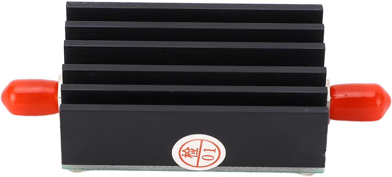
Abbildung 3.1: Vorderseite view der HF-Leistung Amplifier, showing the black heatsink and red protective caps on the SMA connectors.

Abbildung 3.2: Oben view der amplifier, revealing the green printed circuit board (PCB) with various electronic components and screw mounts.

Figure 3.3: A detailed close-up of the PCB, highlighting the RF2126 chip and other surface-mount components.
4. Spezifikationen
| Parameter | Wert |
|---|---|
| Modell | KDT2400B 007 |
| Material | Aluminiumlegierung, Leiterplatte |
| Arbeitsfrequenz | 1500-2600 MHz |
| Gewinnen | 30 dB bei 2000 MHz |
| Stromversorgung | 6 V (450 mA at maximum output power) |
| P1dB Power Compression Point | 30 dBm |
| Maximaler Eingang | 10 dBm |
| Eingangs- / Ausgangsimpedanz | 50 Ω |
| Artikelgewicht | 47 g |
| Verpackungsabmessungen | 13 x 9 x 2 cm |

Figure 4.1: Dimensional drawing of the RF Power Amplifier, indicating approximate measurements of 70mm (2.76in) length, 30mm (1.18in) width, and 16.5mm (0.65in) height for the main body.
5. Einrichtung
The Walfront RF Power Amplifier is designed for straightforward integration. Follow these steps for initial setup:
- Auspacken: Carefully remove the RF Power Amplifier and any included accessories from its packaging.
- Überprüfen: Check the device for any visible damage. If damage is found, do not proceed with setup and contact support.
- Last anschließen: Before applying power, connect a 50 Ω RF load to the output SMA connector (labeled RFOUT). This is crucial to prevent damage to the ampschwerer.
- Eingang anschließen: Connect your RF signal source to the input SMA connector (labeled RFIN).
- Strom anschließen: Connect a stable 6V DC power supply to the designated power input terminals (VIN and GND). Ensure correct polarity. The device requires approximately 450mA at maximum output.
- Sichere Platzierung: Platzieren Sie die amplifier on a stable, non-conductive surface, ensuring adequate airflow around the heatsink.
6. Bedienungsanleitung
Sobald das amplifier is properly set up with a load and input signal, you can begin operation:
- Einschalten: Apply power to the 6V DC input.
- Eingangssignal anlegen: Introduce your RF input signal to the RFIN port. Ensure the input signal level does not exceed 10 dBm to prevent saturation or damage.
- Monitorausgang: Überwachen Sie die amplified output signal from the RFOUT port using appropriate test equipment (e.g., spectrum analyzer, power meter).
- Observe Heat: During operation, especially at higher power levels or prolonged use, the heatsink will become warm. This is normal. If the device becomes excessively hot, reduce the input power or ensure better ventilation.
- Ausschalten: To power down, first remove the input signal, then disconnect the 6V DC power supply.
7. Wartung
The Walfront RF Power Amplifier is designed for low maintenance. Follow these guidelines to ensure its longevity:
- Reinigung: Keep the device clean and free from dust. Use a soft, dry cloth to wipe the exterior. Do not use liquid cleaners or solvents.
- Belüftung: Ensure the heatsink fins remain clear of obstructions to allow for proper heat dissipation. Periodically check for dust buildup in the fins.
- Lagerung: Bei längerer Nichtbenutzung lagern Sie die ampDen Verstärker an einem kühlen, trockenen Ort, fern von direkter Sonneneinstrahlung und extremen Temperaturen aufstellen.
- Verbindungen: Periodically check the SMA connections for tightness and ensure they are free from corrosion.
8. Fehlerbehebung
If you encounter issues with your RF Power AmpBei Problemen mit dem Verstärker konsultieren Sie bitte die folgende Anleitung zur Fehlerbehebung:
| Problem | Mögliche Ursache | Lösung |
|---|---|---|
| Kein Ausgangssignal | No power supply; Incorrect power supply voltage/polarity; No input signal; Damaged unit; Output not connected to load. | Überprüfen Sie den Netzteilanschluss und die Lautstärke.tage (must be 6V); Ensure input signal is present; Always connect a 50 Ω load to the output before powering on. Wenn das Problem weiterhin besteht, wenden Sie sich an den Support. |
| Geringe Ausgangsleistung | Low input signal; Incorrect load impedance; Amplifier operating outside specified frequency range; Overheating. | Increase input signal (up to 10 dBm max); Ensure load is 50 Ω; Verify operating frequency is within 1500-2600 MHz; Ensure proper ventilation. |
| Übermäßige Hitze | Prolonged operation at high power; Insufficient ventilation; Ambient temperature too high. | Reduce input power or duty cycle; Ensure heatsink is clear and has adequate airflow; Operate in a cooler environment. |
| Instabiler Betrieb | Unstable power supply; Loose connections; RF feedback. | Use a stable and regulated 6V power supply; Check all SMA and power connections for tightness; Ensure proper shielding and grounding in your setup to prevent feedback. |
9. Packungsinhalt
- 1 x RF Power Ampschwerer
- 1 x Kabel
10. Unterstützung
For further assistance or inquiries, please contact Walfront customer support through your purchase platform or visit the official Walfront store page on Amazon.
Walfront Store: https://www.amazon.de/stores/WalfrontHeimwerkerWerkzeuge/page/E0CBA462-BF73-4706-86AB-DFB96ED51A28
Ask a question about this manual
Ask about setup, troubleshooting, compatibility, parts, safety, or missing instructions. Manuals+ will review the question and use this page’s manual context to help answer it.