1. Produktüberschreitungview
This document provides comprehensive instructions for the M5Stack STM32-equipped 4-Channel Relay Module V1.1-13.2. This module is the successor to previous STM32-equipped 4-channel relay modules, featuring enhanced capabilities such as external power supply (HPWR) voltage measurement. Designed for use with M5Stack Core and Core2 series products, this compact module measures 13.2 mm in height and integrates four 'a' contact (Normally Open, Common) mechanical relays. It supports the I2C communication protocol and allows for flexible active/passive mode switching via jumpers. The module is compatible with DC power inputs and can handle a maximum load of 24 W (DC 24 V @ 1 A), making it suitable for controlling various small load circuits.

Abbildung 1: Oben view of the M5Stack 4-Channel Relay Module V1.1-13.2, showing the four orange relays and green terminal blocks.
2. Spezifikationen
- Hauptsteuerchip: STM32F030F4
- Kommunikationsschnittstelle: I2C interface (Address: 0x26)
- Unterstützte Betriebsarten: Active Control / Passive Control
- Relais: 4 x (COM, NO terminals) mechanical relays
- Externer Stromeingang: DC 5V bis 24V
- Maximale Belastung: 4 channels, Max 24W (DC 24V @ 1A)
- Anschlussklemmen: 2.54mm pitch 2P terminal block
- Included Terminals: 1 x External Power Input, 4 x Relay (NO, COM) terminals
- Gewicht: 33.2 g
- Abmessungen: 54 x 54 x 13.2 mm
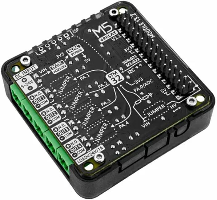
Abbildung 2: Ausführlich view of the module's PCB, showing component layout, pin labels, and jumper settings for various functions including power input and relay connections.
3. Einrichtung und Verbindung
To set up your M5Stack 4-Channel Relay Module, follow these steps:
- Connect to M5Stack Core: Align the module with your M5Stack Core or Core2 series product and gently press to ensure a secure connection via the pin headers.
- Externes Netzteil: Connect a DC power supply (5V to 24V) to the designated external power input terminal block. Ensure correct polarity. This input is labeled "DC INPUT 5-24V" on the PCB.
- Lastverbindungen: Connect your small load circuits to the relay terminals. Each relay has a Normally Open (NO) and Common (COM) terminal. Refer to the PCB labels (e.g., "N.O. OUT1 COM") for correct wiring.
- Jumper-Einstellungen: Configure the jumpers for active or passive control mode as required by your application. Refer to Figure 2 for jumper locations.

Abbildung 3: Mehrere views of the M5Stack 4-Channel Relay Module, illustrating its compact size and various connection points from different angles.
4. Bedienungsanleitung
The M5Stack 4-Channel Relay Module operates via the I2C communication protocol. Your M5Stack Core will send commands to the module to control the state of the four mechanical relays.
- I2C-Kommunikation: The module's I2C address is 0x26. Use the appropriate M5Stack libraries or custom code to send commands to this address to switch relays ON or OFF.
- Active/Passive Mode: The module supports both active and passive control modes. This setting is configured using onboard jumpers. In active mode, the module might provide power to the relays, while in passive mode, an external power source is typically required for the relay coils. Consult the module's schematic or specific M5Stack documentation for detailed jumper configurations.
- Relaissteuerung: Each relay can be independently controlled. When a relay is activated, the Normally Open (NO) contact will close, completing the circuit for the connected load.
5. Wartung
The M5Stack 4-Channel Relay Module is designed for durability and requires minimal maintenance.
- Reinigung: Keep the module free from dust and debris. Use a soft, dry cloth for cleaning. Avoid using liquid cleaners or solvents.
- Lagerung: Lagern Sie das Modul an einem trockenen, kühlen Ort, geschützt vor direkter Sonneneinstrahlung und extremen Temperaturen.
- Handhabung: Handle the module with care to avoid physical damage to the PCB or components. Avoid static discharge by handling in an ESD-safe environment.
6. Fehlerbehebung
If you encounter issues with your M5Stack 4-Channel Relay Module, consider the following troubleshooting steps:
- Modul reagiert nicht:
- Ensure the module is securely connected to the M5Stack Core.
- Verify the external power supply is connected and providing the correct voltage (5V-24V DC).
- Check your I2C communication code and ensure the correct address (0x26) is being used.
- Relays Not Switching:
- Confirm that the load connected to the relay does not exceed the maximum rating of 24W (DC 24V @ 1A).
- Check the wiring to the NO and COM terminals for continuity and correct connection.
- Inspect jumper settings for active/passive mode to ensure they match your power configuration.
- Falsche Lautstärketage-Messung:
- Ensure the HPWR connection for voltage measurement is correctly established.
- Verify the external power supply voltage with a multimeter to rule out issues with the source.
7. Garantie und Support
This product is manufactured by M5STACK. For specific warranty information, please refer to the documentation provided at the time of purchase or visit the official M5STACK webWebsite.
For technical support, programming guides, and community forums, please visit the official M5Stack documentation portal or contact your local distributor.
- Offizieller M5Stack WebWebsite: https://m5stack.com/
- Dokumentation: https://docs.m5stack.com/