1. Sicherheitshinweise
Please read and understand all safety information before operating this multimeter. Failure to follow these instructions may result in electric shock, fire, or damage to the meter or the equipment under test.
- Stellen Sie stets sicher, dass die Messleitungen in gutem Zustand und ordnungsgemäß angeschlossen sind.
- Nicht anwenden voltage or current that exceeds the maximum rated values for the meter.
- Seien Sie vorsichtig beim Arbeiten mit VolumentagEs liegt über 30 V AC RMS, 42 V Spitze oder 60 V DC. Diese SpannungentagEs besteht die Gefahr eines Stromschlags.
- Vor der Strommessung muss sichergestellt werden, dass der Stromkreis spannungsfrei ist und das Messgerät in Reihe geschaltet ist.
- Trennen Sie vor dem Ändern von Funktionen die Messleitungen vom zu testenden Stromkreis.
- Das Messgerät darf nicht bedient werden, wenn es beschädigt erscheint oder der Batteriedeckel nicht ordnungsgemäß geschlossen ist.
- Tauschen Sie die Batterie sofort aus, wenn die Anzeige für niedrigen Batteriestand erscheint.
- Halten Sie sich an lokale und nationale Sicherheitsvorschriften.
2. Produktüberschreitungview
The UOFKIPBA DT-118 is a compact, auto-ranging digital multimeter designed for high-precision measurements in industrial, automotive, and household applications. It features an automatic digital display and a durable design.
2.1 Komponenten
Familiarize yourself with the main components of your DT-118 multimeter:
- LCD Anzeige: Zeigt Messwerte, Einheiten und Funktionsindikatoren an.
- Funktionsdrehschalter: Dient zur Auswahl der gewünschten Messfunktion (Vol.)tage, Current, Resistance, etc.) and to turn the meter OFF.
- Eingangsbuchsen: Terminals for connecting test leads.
- MODE-Taste: Toggles between different measurement modes within a function (e.g., AC/DC voltagUnd).
- Halte den Knopf: Friert den aktuellen Anzeigewert ein.
- Backlight Button (Light Bulb Icon): Aktiviert oder deaktiviert die Display-Hintergrundbeleuchtung.

Abbildung 2.1: Vorderseite view of the UOFKIPBA DT-118 Digital Multimeter, showing the display, rotary switch, and function buttons.

Figure 2.2: The DT-118 multimeter displaying "0.00 mA", highlighting its automatic digital display capability for household use.
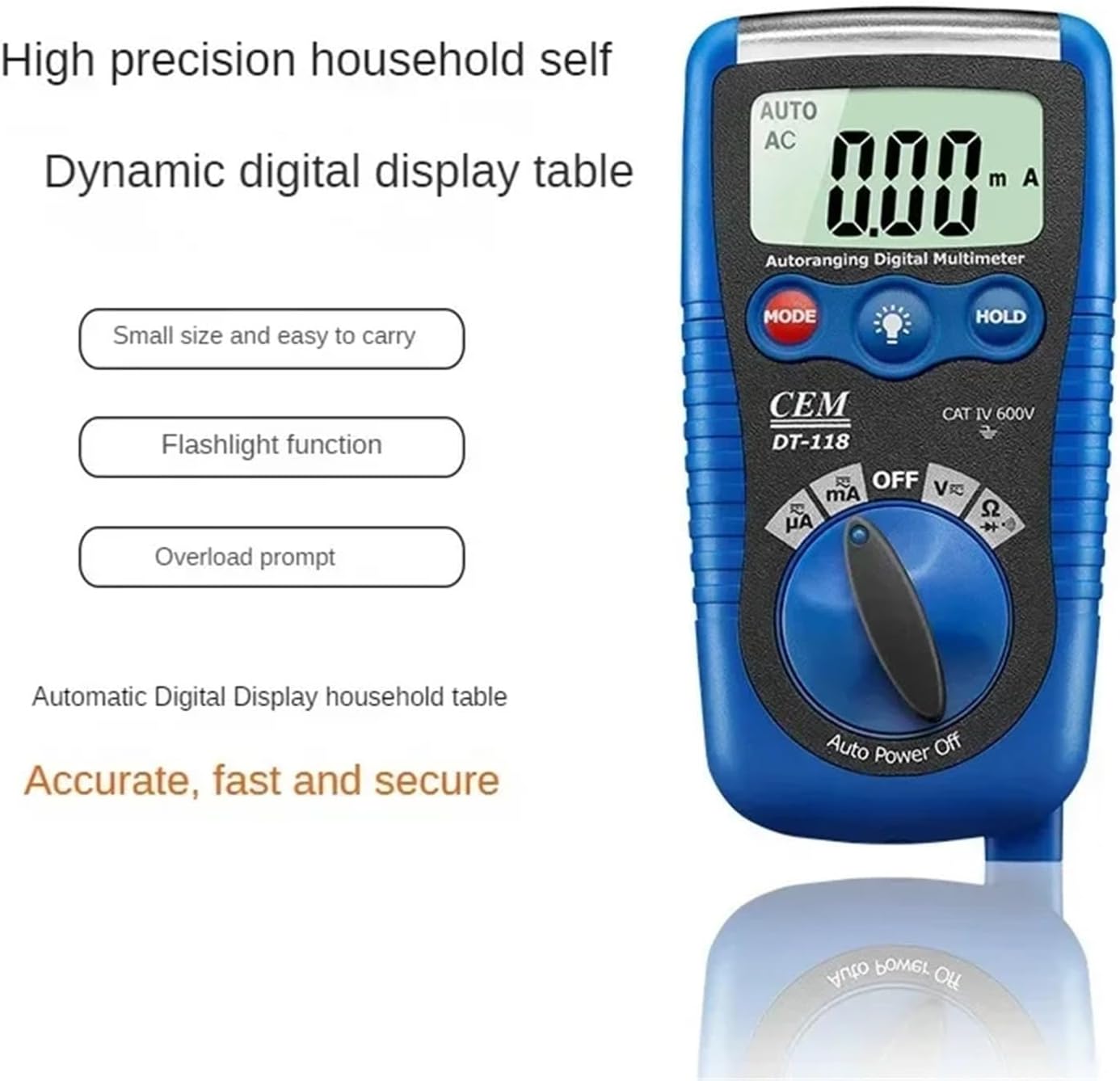
Figure 2.3: The DT-118 multimeter emphasizing its features: small size, easy to carry, flashlight function, and overload prompt for accurate, fast, and secure measurements.
3. Einrichtung
3.1 Einlegen der Batterie
The DT-118 multimeter requires batteries for operation. Follow these steps to install or replace the batteries:
- Stellen Sie sicher, dass das Multimeter ausgeschaltet ist und trennen Sie alle Messleitungen.
- Suchen Sie den Batteriefachdeckel auf der Rückseite des Messgeräts.
- Verwenden Sie einen Schraubendreher, um die Schraube(n) zu lösen, mit der/denen die Abdeckung befestigt ist/sind.
- Remove the cover and insert new batteries, observing the correct polarity (+ and -).
- Bringen Sie die Abdeckung des Batteriefachs wieder an und ziehen Sie die Schraube(n) fest.
3.2 Anschließen der Testleitungen
Für genaue und sichere Messungen ist der korrekte Anschluss der Messleitungen unerlässlich.
- Stecken Sie die schwarze Messleitung in die "COM" (Common) Eingangsbuchse.
- Für die meisten Messungen (Vol)tage, Resistance, Diode, Continuity, small Current), insert the red test lead into the "VΩmA" input jack.
- For high current measurements (if applicable and supported by the model), refer to the specific input jack labeled for higher current (e.g., "10A" or "20A"). The DT-118 typically uses a single mA input for current.

Figure 3.1: The DT-118 multimeter with its red and black test leads properly connected to the input jacks, ready for use.
4. Bedienung
This section describes how to use the DT-118 multimeter for various measurements.
4.1 Messen der Gleichspannungtage (V=)
- Turn the rotary switch to the "V" position. The meter will automatically select DC voltage. If it defaults to AC, press the MODE button to switch to DC.
- Verbinden Sie die rote Prüfleitung mit dem Pluspol (+) des Stromkreises und die schwarze Prüfleitung mit dem Minuspol (-).
- Lesen Sie den Bandtage-Wert auf dem LCD-Display.
4.2 Messen der Wechselspannungtage (V~)
- Turn the rotary switch to the "V" position. The meter will automatically select AC voltage. If it defaults to DC, press the MODE button to switch to AC.
- Schließen Sie die Messleitungen an den zu messenden Stromkreis oder das zu messende Bauteil an.
- Lesen Sie den Bandtage-Wert auf dem LCD-Display.
4.3 Widerstandsmessung (Ω)
- Vor der Widerstandsmessung muss sichergestellt werden, dass der Stromkreis spannungsfrei ist.
- Drehen Sie den Drehschalter auf die Position "Ω".
- Schließen Sie die Messleitungen an das Bauteil an, dessen Widerstand Sie messen möchten.
- Lesen Sie den Widerstandswert auf dem LCD-Display ab.
4.4 Measuring Current (mA)
Vorsicht: Schließen Sie das Multimeter niemals parallel zu einem Spannungsregler an.tagDie Stromquelle beim Messen des Stroms nicht berühren, da dies das Messgerät und den Stromkreis beschädigen kann.
- Stellen Sie sicher, dass der Stromkreis spannungsfrei ist.
- Turn the rotary switch to the "mA" position. Press MODE to select AC or DC current if necessary.
- Break the circuit and connect the multimeter in series with the load. The current must flow through the meter.
- Schalten Sie den Stromkreis wieder ein und lesen Sie den aktuellen Wert auf dem LCD-Display ab.
4.5 Diodentest (→|) and Continuity Test (🔊)
- Stellen Sie sicher, dass der Stromkreis spannungsfrei ist.
- Turn the rotary switch to the "Ω" position. Press the MODE button until the diode symbol (→|) or continuity symbol (🔊) erscheint auf dem Display.
- Diodentest: Schließen Sie die rote Leitung an die Anode und die schwarze Leitung an die Kathode der Diode an. Eine Durchlassspannungtage drop will be displayed. Reverse the leads; an "OL" (Open Loop) or very high reading indicates a good diode.
- Durchgangsprüfung: Connect the test leads across the component or wire. If there is continuity (low resistance), the meter will emit an audible beep.
5. Wartung
Proper maintenance ensures the longevity and accuracy of your DT-118 multimeter.
5.1 Reinigung
- Disconnect the meter from all circuits and turn it OFF.
- Löschen Sie den Fall mit Anzeigeamp cloth and a mild detergent. Do not use abrasives or solvents.
- Stellen Sie sicher, dass das Messgerät vor Gebrauch vollständig trocken ist.
5.2 Batteriewechsel
When the low battery indicator appears on the display, replace the batteries as described in Section 3.1. Always use the specified battery type.
5.3 Sicherungswechsel
If the current measurement function stops working, the fuse may need replacement. Refer to the specifications for the correct fuse type and rating. Fuse replacement typically involves opening the back case of the meter (similar to battery replacement) and carefully replacing the blown fuse with a new one of the exact same rating.
Warnung: Always replace fuses with those of the specified type and rating to prevent damage to the meter or personal injury.
6. Fehlerbehebung
This section addresses common issues you might encounter with your DT-118 multimeter.
| Problem | Mögliche Ursache | Lösung |
|---|---|---|
| Der Zähler schaltet sich nicht ein. | Defekte oder falsch eingesetzte Batterien. | Batteriepolarität prüfen; Batterien austauschen. |
| „OL“ (Überlastung) wird angezeigt. | Measurement exceeds meter's range; open circuit. | Select a higher range (if not auto-ranging); check for open circuit in resistance/continuity. |
| Falsche Messwerte. | Wrong function selected; poor test lead connection; low battery. | Verify function selection; ensure leads are firmly connected; replace batteries. |
| Strommessung funktioniert nicht. | Blown fuse; incorrect connection (not in series). | Check and replace fuse (Section 5.3); ensure meter is connected in series with the load. |
7. Spezifikationen
The following are the general specifications for the UOFKIPBA DT-118 Digital Multimeter. Specific ranges and accuracies may vary slightly.
- Modell: DT-118
- Anzeige: Automatic Digital Display
- Sicherheitsbewertung: KAT IV 600V
- DC-Voltage: Range typically up to 600V
- AC-Lautstärketage: Range typically up to 600V
- Gleichstrom: Range typically up to 200mA
- Wechselstrom: Range typically up to 200mA
- Widerstand: Range typically up to 20MΩ
- Diodentest: Ja
- Durchgangsprüfung: Ja (mit Summer)
- Leistung: Battery operated (specific type not provided, assume common multimeter batteries like AAA or 9V)
- Abmessungen: Approximately 1.18 x 0.79 x 0.39 inches (Package Dimensions, actual product might be slightly different but gives an idea of compact size)
- Gewicht: Ungefähr 1.76 Unzen (50 Gramm)
- Merkmale: Auto-ranging, Data Hold, Backlight, Auto Power Off, Overload Prompt, Flashlight Function.
8. Garantie und Support
For warranty information or technical support regarding your UOFKIPBA DT-118 Digital Multimeter, please contact the retailer or manufacturer directly. Keep your purchase receipt as proof of purchase.
Manufacturer: UOFKIPBA