
1. Produktüberschreitungview
The Zunate X99H Motherboard is designed for high-performance desktop computing, supporting LGA 2011-3 CPUs including E5 V3, E5 V4, i7 58xx, and i7 68xx series processors. It features four DDR4 DIMM slots, allowing for a maximum memory capacity of 128GB, with support for DDR4 2666, 2400, and 2133MHz memory types. This mATX form factor motherboard includes M.2 NVMe and SATA3 interfaces for storage, USB 3.0 connectivity, and integrated HD multimedia and VGA interfaces for display output. The design incorporates solid capacitors for enhanced stability and extended lifespan.

Figure 1: Zunate X99H Motherboard - Top View. This image displays the overall layout of the motherboard, including the LGA 2011-3 CPU socket, four DDR4 DIMM slots, PCIe slots, and various headers and ports.
2. Einrichtung und Installation
Follow these steps for proper installation of your Zunate X99H Motherboard and its components.
2.1 CPU-Installation
- Bereiten Sie den CPU-Sockel vor: Gently lift the CPU retention lever on the LGA 2011-3 socket.
- Richten Sie die CPU aus: Carefully align your LGA 2011-3 CPU (E5 V3/V4, i7 58xx/68xx series) with the socket, ensuring the triangular markers on the CPU and socket match. Do not force the CPU into place.
- CPU sichern: Lower the CPU into the socket. Close the retention lever until it clicks into place.
- CPU-Kühler installieren: Apply thermal paste (if not pre-applied) and install your compatible CPU cooler according to its manufacturer's instructions.

Figure 2: CPU Socket Compatibility. This image emphasizes the LGA 2011-3 CPU socket, compatible with E5 V3/V4 and i7 58xx/68xx series processors, and shows the 8-pin and 24-pin power sockets.
2.2 Installation des Arbeitsspeichers (RAM)
- Open DIMM Latches: Open the retention clips at both ends of the DDR4 DIMM slots.
- Align RAM Modules: Richten Sie die Kerbe an Ihrem DDR4-Speichermodul an der entsprechenden Aussparung im DIMM-Steckplatz aus.
- RAM einsetzen: Drücken Sie beide Enden des Speichermoduls fest nach unten, bis die Halteklammern einrasten.
- Install Multiple Modules: For optimal performance, refer to your CPU and memory manufacturer's guidelines for dual or quad-channel memory configuration.

Figure 3: Memory Support. This image highlights the four DDR4 DIMM slots, capable of supporting up to 128GB of DDR4 2666/2400/2133MHz memory.
2.3 Installation des Speichergeräts
- M.2 NVMe/SATA SSD:
- Suchen Sie den M.2-Steckplatz auf der Hauptplatine.
- Setzen Sie die M.2 SSD schräg in den Steckplatz ein.
- Drücken Sie die SSD vorsichtig nach unten und befestigen Sie sie mit der mitgelieferten Schraube.
- Ensure the jumper switch for the M.2 interface is set correctly for either Serial ATA or PCIE protocol, depending on your M.2 device.
- Serial ATA (SATA) Devices:
- Connect one end of a SATA data cable to a SATA port on the motherboard (2 x SATA2.0, 1 x SATA3.0).
- Verbinden Sie das andere Ende des SATA-Datenkabels mit Ihrer SATA-Festplatte oder SSD.
- Verbinden Sie ein SATA-Stromkabel von Ihrem Netzteil (PSU) mit dem SATA-Gerät.
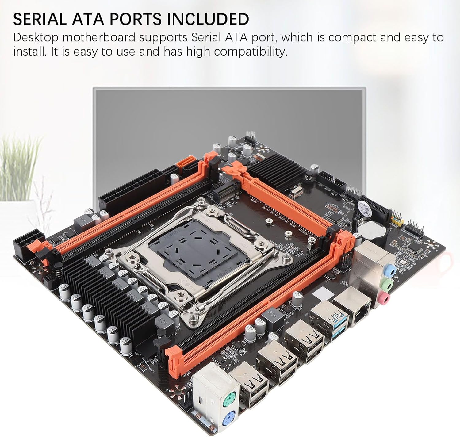
Figure 4: Storage Connectivity. This image shows the Serial ATA ports and the M.2 slot, supporting NGFF and NVME protocols for various storage solutions.
2.4 Stromanschlüsse
- 24-poliger ATX-Stromanschluss: Connect the main 24-pin power cable from your PSU to the 24-pin power socket on the motherboard.
- 8-poliger CPU-Stromanschluss: Connect the 8-pin (or 4+4 pin) CPU power cable from your PSU to the 8-pin power socket near the CPU.
2.5 Periphere Verbindungen
- Grafikkarte: Insert your PCI Express 16X graphics card into the designated slot and secure it.
- Frontplattenanschlüsse: Connect the power switch, reset switch, HDD LED, power LED, and front panel USB/audio headers to their respective pins on the motherboard. Refer to the motherboard's silkscreen labels for correct orientation.
- USB-Geräte: Connect USB 2.0 and USB 3.0 devices to the rear I/O panel ports.
- Netzwerk: Connect an Ethernet cable to the RJ45 network interface.
- Anzeige: Connect your monitor to the graphics card or the integrated HD multimedia/VGA interfaces if using integrated graphics (CPU dependent).

Figure 5: Rear I/O Panel. This image provides a clear view of the motherboard's rear input/output ports, including USB 2.0, USB 3.0, RJ45 network, and audio jacks.
3. Bedienungsanleitung
Sobald alle Komponenten installiert und angeschlossen sind, können Sie Ihr System einschalten.
- Erstes Einschalten: Ensure all power cables are securely connected. Press the power button on your PC case.
- BIOS/UEFI-Zugriff: During startup, repeatedly press the designated key (commonly DEL, F2, oder F10) to enter the BIOS/UEFI setup utility. Here you can configure boot order, system time, and other advanced settings.
- Installation des Betriebssystems: Legen Sie Ihr Installationsmedium für das Betriebssystem (USB-Stick oder DVD) ein und folgen Sie den Anweisungen auf dem Bildschirm, um Ihr bevorzugtes Betriebssystem zu installieren.
- Treiberinstallation: After OS installation, install the necessary drivers for your motherboard (chipset, network, audio, USB, etc.) from the manufacturer's webWebsite oder bereitgestellte Medien.
4. Wartung
Regelmäßige Wartung trägt dazu bei, die Langlebigkeit und die stabile Leistung Ihres Motherboards und PC-Systems zu gewährleisten.
- Staubentfernung: Periodically clean dust from inside your PC case, especially from fans, heatsinks, and motherboard components, using compressed air. Ensure the system is powered off and unplugged before cleaning.
- Kabelmanagement: Sorgen Sie für eine ordentliche Verlegung der internen Kabel, um die Luftzirkulation zu verbessern und Verstopfungen zu vermeiden.
- BIOS/UEFI-Updates: Überprüfen Sie die Angaben des Herstellers webWebsite für BIOS/UEFI-Updates. Updates können Kompatibilität, Stabilität und Leistung verbessern. Befolgen Sie die Update-Anweisungen sorgfältig.
- Komponentenprüfungen: Occasionally check that all components (RAM, graphics card, storage drives) are securely seated in their slots.

Figure 6: Stable Performance Components. This image highlights the solid capacitors used on the motherboard, contributing to its stability and extended lifespan.
5. Fehlerbehebung
Sollten Probleme auftreten, beachten Sie die folgenden gängigen Schritte zur Fehlerbehebung:
- Kein Strom:
- Stellen Sie sicher, dass das Netzteil eingeschaltet und an eine funktionierende Steckdose angeschlossen ist.
- Verify that the 24-pin and 8-pin power cables are securely connected to the motherboard.
- Überprüfen Sie die Verbindung des Netzschalters an der Vorderseite mit dem Motherboard.
- Kein Bildschirm:
- Confirm that your monitor is connected to the correct display output (graphics card or integrated graphics port).
- Setzen Sie die Grafikkarte und die RAM-Module neu ein.
- Test with a single RAM module in different slots.
- Ensure the CPU cooler is properly installed and connected.
- Systeminstabilität/Abstürze:
- Prüfen Sie auf Überhitzung. Stellen Sie sicher, dass der CPU-Kühler und die Gehäuselüfter funktionieren.
- Verify RAM compatibility and stability (e.g., run memory diagnostic tools).
- Stellen Sie sicher, dass alle Treiber auf dem neuesten Stand sind.
- Prüfen Sie, ob Strom- oder Datenkabel lose sind.
- Speicher nicht erkannt:
- For SATA drives, check data and power cable connections.
- For M.2 drives, ensure it is fully seated and secured, and the M.2 jumper is set correctly for its protocol (NVMe or SATA).
- Check BIOS/UEFI settings to ensure SATA ports are enabled and M.2 detection is configured.

Figure 7: Expansion Capabilities. This image highlights the M.2 slot, supporting NGFF and NVME protocols, and other expansion slots like PCIe x16 and PCIe x1, along with HD multimedia and VGA interfaces.
6. Spezifikationen
| Besonderheit | Spezifikation |
|---|---|
| Motherboard Structure | M-ATX |
| Chipsatz | X99H |
| CPU-Sockel | LGA 2011-3 |
| Supported CPU Types | Intel E5 V3/V4 series, i7 58xx/68xx series |
| Memory Slots | 4 x DDR4 DIMM |
| Maximale Speicherkapazität | 128 GB |
| Speichertypen | DDR4 2666MHz, 2400MHz, 2133MHz |
| Onboard-Netzwerkkarte | Yes (RJ45 interface) |
| Grafikkartensteckplatz | 1 x PCI Express 16X |
| Erweiterungssteckplätze | 1 x PCIE x1, 1 x NVME M.2 Interface (Serial ATA, PCIE with Jumper Switch) |
| USB Interfaces (Rear) | 6 x USB 2.0, 2 x USB 3.0 |
| USB Pins (Internal) | 1 set USB3.0, 1 set USB2.0 |
| Serial ATA Ports | 2 x Serial ATA2.0, 1 x Serial ATA3.0 |
| Steckdosen | 1 x 8-pin, 1 x 24-pin |
| Eingebauter Akku | CR2032x1 240mah |
| I / O-Schnittstellen | PS/2 Keyboard/Mouse Universal Interface, 1 x RJ45 Network Interface, HD multimedia, VGA |
7. Garantie und Support
For warranty information and technical support, please refer to the official Zunate webWebsite oder wenden Sie sich an Ihren Händler.
- Hersteller: Zunate
- Modellnummer: Zunatear2wnouip9
- Online-Hilfe: Besuchen Sie die Zunate Store on Amazon for product information and potential support links. For direct manufacturer support, search for "Zunate official webWebsite online.
- Rückgaberecht: This product may be subject to a 30-day return/replacement policy. Please check with your retailer for specific details.