1. Einleitung
This manual provides essential information for the installation, configuration, operation, and maintenance of your Zyyini X99H Motherboard Kit. Please read these instructions carefully before proceeding with installation to ensure proper setup and optimal performance. Retain this manual for future reference.
2. Produktüberschreitungview
The Zyyini X99H Motherboard is designed for high-performance computing, offering robust compatibility and expansion options. It supports a range of CPUs and memory configurations, making it suitable for various computing needs.
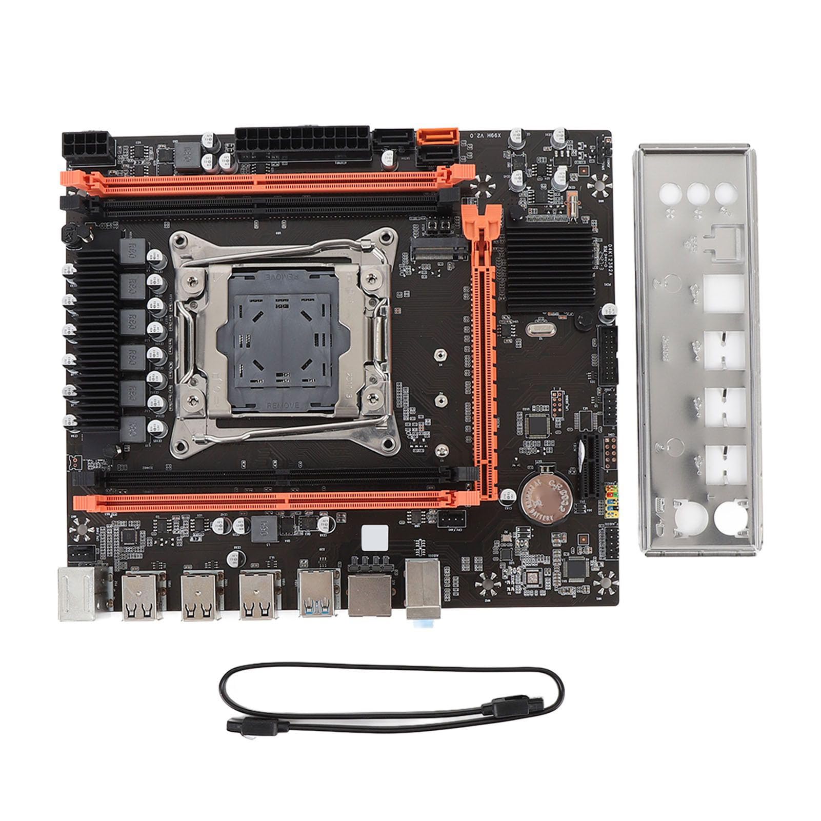
Abbildung 2.1: Überview of the Zyyini X99H Motherboard Kit.
Hauptmerkmale:
- Starke Kompatibilität: Features an LGA 2011-3 CPU socket, supporting Intel E5 V3/V4 and i7 58xx/68xx series processors. Includes one 8-pin and one 24-pin power socket for stable power delivery.
- Impressive Memory Support: Equipped with four DDR4 DIMM slots, supporting up to 128GB of DDR4 memory at speeds of 2666, 2400, or 2133MHz.
- Serial ATA Ports: Includes Serial ATA ports for compact and easy storage device installation, ensuring high compatibility.
- Stabile Leistung: Utilizes all solid capacitors for enhanced stability and extended operational lifespan, contributing to reliable motherboard performance.
- Einfache Erweiterung: Provides HD multimedia (HDMI) and VGA interfaces for display output, along with an M.2 slot that supports both NGFF and NVME protocols for high-speed storage expansion. It also features a PCI Express 16X slot for graphics cards.
3. Spezifikationen
Below are the detailed technical specifications for the Zyyini X99H Motherboard Kit:

Abbildung 3.1: Draufsicht view of the Zyyini X99H Motherboard, highlighting component layout.
| Besonderheit | Spezifikation |
|---|---|
| Motherboard Structure | M-ATX |
| Chipsatz | X99H |
| CPU-Sockel | LGA 2011-3 |
| Supported CPU Types | Intel E5 V3/V4, i7 58xx/68xx series |
| Speichertyp | DDR4 2666/2400/2133 MHz |
| Memory Slots | 4 x DDR4 DIMM |
| Maximale Speicherkapazität | 128 GB |
| Graphics Card Standard Support | PCI Express 16X |
| Erweiterungssteckplätze | 1 x PCIE x16, 1 x PCIE x1, 1 x NVME M.2 Interface (Serial ATA, PCIE with Jumper Switch) |
| USB Schnittstellen | 6 x USB 2.0, 2 x USB 3.0 (rear I/O), USB3.0 Pins (1 Set), USB2.0 Pins (1 Set) |
| Serial ATA Ports | 2 x Serial ATA 2.0, 1 x Serial ATA 3.0 |
| Videoausgänge | HDMI, VGA |
| Netzwerkschnittstelle | 1 x RJ45 |
| PS/2-Schnittstelle | 1 x PS/2 Keyboard/Mouse Universal Interface |
| Eingebauter Akku | CR2032x1 240mah |
4. Einrichtung und Installation
Eine korrekte Installation ist entscheidend für die Stabilität und Leistung Ihres Systems. Befolgen Sie diese Schritte sorgfältig.
4.1. Vorbereitung
- Sorgen Sie für einen sauberen und gut beleuchteten Arbeitsplatz.
- Benötigte Werkzeuge bereithalten: Kreuzschlitzschraubendreher, antistatisches Armband (empfohlen).
- Vor der Handhabung der Bauteile statische Elektrizität durch Berühren eines geerdeten Metallgegenstands ableiten.
4.2. CPU-Installation
Carefully install your LGA 2011-3 processor into the CPU socket.
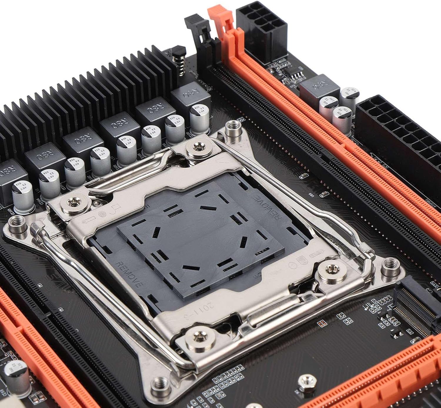
Abbildung 4.1: Nahaufnahme view of the LGA 2011-3 CPU socket.
- Öffnen Sie den Haltemechanismus des CPU-Sockels.
- Richten Sie die CPU am Sockel aus und achten Sie darauf, dass das goldene Dreieck auf der CPU mit der Markierung am Sockel übereinstimmt.
- Setzen Sie die CPU vorsichtig in den Sockel ein, ohne sie mit Gewalt einzusetzen.
- Schließen Sie den Verriegelungsmechanismus, um die CPU zu sichern.
- Installieren Sie den CPU-Kühler gemäß den Anweisungen des Herstellers.
4.3. RAM-Installation
Installieren Sie DDR4-Speichermodule in die DIMM-Steckplätze.
- Öffnen Sie die Klemmen an beiden Enden der DIMM-Steckplätze.
- Richten Sie das Speichermodul am Steckplatz aus und achten Sie darauf, dass die Kerbe am Modul mit der entsprechenden Markierung im Steckplatz übereinstimmt.
- Drücken Sie beide Enden des Speichermoduls fest nach unten, bis die Klammern einrasten.
4.4. Montage des Motherboards
Mount the motherboard into your PC case.
- Montieren Sie die I/O-Blende in die hintere Öffnung des Gehäuses.
- Align the motherboard with the standoffs in your PC case.
- Befestigen Sie das Motherboard mit Schrauben.
4.5. Stromversorgung anschließen
Schließen Sie die Kabel des Netzteils (PSU) an das Motherboard an.
- Connect the 24-pin ATX power cable to the main power connector.
- Connect the 8-pin CPU power cable to the CPU power connector.
4.6. Connecting Storage Devices
Connect your SATA and NVME M.2 storage devices.

Abbildung 4.2: Nahaufnahme view of the M.2 slot and SATA ports.
- For SATA drives, connect one end of the SATA data cable to the motherboard's SATA port and the other to the drive. Connect the SATA power cable from the PSU to the drive.
- For NVME M.2 SSDs, insert the M.2 module into the M.2 slot and secure it with the provided screw.
4.7. Anschließen von Peripheriegeräten und Frontplatte
Connect USB devices, front panel connectors, and other I/O.

Abbildung 4.3: Nahaufnahme view of the rear I/O ports.
- Connect your mouse and keyboard to the PS/2 or USB ports.
- Connect front panel USB, audio, power switch, reset switch, and LED indicators to the corresponding headers on the motherboard. Refer to your PC case manual for specific pin assignments.
- Connect network cables to the RJ45 port.
4.8. Grafikkarteninstallation
Install your PCI Express graphics card.
- Öffnen Sie die Halteklammer am PCIe x16-Steckplatz.
- Richten Sie die Grafikkarte am Steckplatz aus und drücken Sie sie fest nach unten, bis sie einrastet.
- Befestigen Sie die Grafikkarte mit einer Schraube am Gehäuse.
- Schließen Sie alle erforderlichen PCIe-Stromkabel vom Netzteil an die Grafikkarte an.
5. Bedienungsanleitung
Once all components are installed, you can proceed with powering on your system.
5.1. Erster Start
- Ensure all power cables are securely connected and the power supply is switched on.
- Drücken Sie den Netzschalter an Ihrem PC-Gehäuse.
- Das System sollte sich einschalten, und Sie sollten ein Bild auf Ihrem Monitor sehen.
5.2. BIOS/UEFI-Zugriff
The BIOS (Basic Input/Output System) or UEFI (Unified Extensible Firmware Interface) allows you to configure fundamental system settings.
- Drücken Sie während des Systemstarts wiederholt die angegebene Taste (üblicherweise DEL, F2, F10, oder F12) um das BIOS/UEFI-Setup-Dienstprogramm aufzurufen.
- Within the BIOS/UEFI, you can adjust boot order, system time, fan speeds, and other hardware-related settings.
5.3. Treiberinstallation
After installing your operating system, install the necessary drivers for your motherboard and other components.
- Obtain the latest drivers from the Zyyini website or the component manufacturers' websites (e.g., chipset, audio, LAN, graphics card).
- Install drivers in the recommended order (typically chipset first, then graphics, audio, LAN, etc.).
5.4. Installation des Betriebssystems
Installieren Sie Ihr bevorzugtes Betriebssystem (z. B. Windows, Linux) von einem bootfähigen USB-Stick oder einer DVD.
- Configure the boot order in BIOS/UEFI to prioritize your installation media.
- Follow the on-screen instructions of your operating system installer.
6. Wartung
Regelmäßige Wartung trägt dazu bei, die Langlebigkeit und den stabilen Betrieb Ihres Motherboards und Systems zu gewährleisten.
- Halte es sauber: Periodically clean dust from inside your PC case, especially around fans and heatsinks, using compressed air. Ensure the system is powered off and unplugged before cleaning.
- Verbindungen prüfen: Occasionally verify that all cables (power, data, peripheral) are securely connected to the motherboard and other components.
- BIOS/UEFI-Updates: Check the Zyyini support webWebsite für BIOS/UEFI-Updates. Updates können Kompatibilität, Stabilität und Leistung verbessern. Befolgen Sie die Update-Anweisungen sorgfältig, um Systemschäden zu vermeiden.
- Software-Updates: Halten Sie Ihr Betriebssystem und Ihre Treiber auf dem neuesten Stand, um optimale Leistung und Sicherheit zu gewährleisten.
7. Fehlerbehebung
Dieser Abschnitt bietet Lösungen für häufig auftretende Probleme.
7.1. No Power / System Does Not Turn On
- Stromanschlüsse prüfen: Ensure the 24-pin ATX and 8-pin CPU power cables are firmly connected to the motherboard and the power supply.
- Netzteilschalter: Verify that the power switch on the PSU is in the 'ON' position.
- Frontplattenanschlüsse: Double-check the power switch connector on the motherboard's front panel header.
- Steckdose: Prüfen Sie die Steckdose mit einem anderen Gerät, um sicherzustellen, dass sie Strom liefert.
7.2. Kein Bild auf dem Monitor
- Monitorverbindung: Ensure the display cable (HDMI/VGA) is securely connected to both the graphics card/motherboard and the monitor.
- Grafikkarte: If using a dedicated graphics card, ensure it is properly seated in the PCIe slot and any required power cables are connected.
- RAM: Setzen Sie die RAM-Module neu ein. Versuchen Sie, den Computer mit nur einem RAM-Riegel zu starten, falls Sie mehrere haben.
- CPU: Ensure the CPU is correctly installed and the CPU cooler is making proper contact.
7.3. Systeminstabilität / Zufällige Abstürze
- Überhitzung: Check CPU and GPU temperatures. Ensure all fans are working correctly and heatsinks are free of dust.
- RAM-Probleme: Run a memory diagnostic tool (e.g., Windows Memory Diagnostic) to check for faulty RAM.
- Treiberprobleme: Stellen Sie sicher, dass alle Treiber aktuell und korrekt installiert sind.
- Stromversorgung: An insufficient or failing power supply can cause instability.
7.4. Component Not Detected (e.g., Storage, USB Device)
- Verbindungen prüfen: Verify that the component's power and data cables are securely connected.
- BIOS/UEFI-Einstellungen: Check if the component is enabled in the BIOS/UEFI settings. For M.2 drives, ensure the correct protocol (NVME/SATA) is selected if applicable via jumper switch.
- Treiber: Install the latest drivers for the component.
- Geräte-Manager: In your operating system, check Device Manager (Windows) or equivalent to see if the device is listed, even with an error.
8. Support und Garantie
For technical support or warranty inquiries, please contact Zyyini customer service through the retailer where you purchased the product or visit the official Zyyini support website. Please have your product model (X99H) and purchase information ready when contacting support.
Specific warranty terms and conditions may vary by region and retailer. Please refer to your purchase documentation for detailed warranty information.