1. Einleitung
This manual provides essential information for the safe and effective operation, assembly, maintenance, and troubleshooting of your Einhell BT-BD 501 Pillar Drill. Please read these instructions carefully before using the product and keep them for future reference.
The Einhell BT-BD 501 is a 500 W pillar drill featuring a 3-16 mm geared chuck, 9 speed settings (280 - 2,350 min-1), a B16 chuck mount, 115 mm throat depth, and a tiltable and rotatable work table with a maximum drilling depth of 50 mm.
2. Sicherheitshinweise
Sicherheit hat beim Umgang mit Elektrowerkzeugen stets oberste Priorität. Die Nichtbeachtung dieser Anweisungen kann zu schweren Verletzungen oder Schäden am Werkzeug führen.
- Lesen Sie das Handbuch: Machen Sie sich vor der Benutzung mit allen Bedienelementen, Einstellungen und Arbeitsabläufen vertraut.
- Tragen Sie persönliche Schutzausrüstung (PSA): Always wear safety glasses or goggles. Hearing protection and a dust mask are also recommended, especially during prolonged use or when drilling materials that produce fine dust.
- Werkstück sichern: Immer clamp the workpiece firmly to the drill table. Never hold it by hand, as it can spin violently and cause injury.
- Halten Sie die Hände frei: Keep hands and fingers away from the rotating drill bit and chuck.
- Vor der Justierung vom Stromnetz trennen: Disconnect the drill from the power supply before changing drill bits, making adjustments, or performing any maintenance.
- Halten Sie Ihren Arbeitsbereich sauber: Keep your work area well-lit and free of clutter.
- Use Correct Drill Bits: Ensure the drill bit is sharp, correctly sized for the chuck, and suitable for the material being drilled.
- Überforderung vermeiden: Achten Sie jederzeit auf sicheren Stand und Gleichgewicht.
- Auf Schäden prüfen: Before each use, inspect the drill for any damaged parts. Do not operate if damaged.
- Not-Halt: Know the location of the power switch and how to quickly turn off the machine in an emergency.
3. Produktkomponenten
The Einhell BT-BD 501 Pillar Drill consists of several key components:
- Base Plate
- Spalte
- Work Table (adjustable height, tilt, and rotation)
- Drill Head (motor, spindle, chuck)
- Spannfutterschutz
- Tiefenstopp
- Feed-Griffe
- Speed Adjustment Mechanism (belt drive)
- Netzschalter

Abbildung 1: Überview of the Einhell BT-BD 501 Pillar Drill.
4. Aufbau und Montage
The assembly of the Einhell BT-BD 501 Pillar Drill is designed to be straightforward. Follow these steps:
- Auspacken: Carefully remove all components from the packaging. Note that parts may be coated with industrial oil for rust prevention; clean these thoroughly before assembly.
- Sockel- und Säulenmontage: Secure the column to the base plate using the provided screws.
- Montage des Arbeitstisches: Slide the work table onto the column and secure it at the desired height.
- Drill Head Mounting: Place the drill head assembly onto the top of the column and fasten it securely.
- Feed Handle Attachment: Screw the three feed handles into the drill head to control the spindle movement.
- Montage des Spannfutters:
- Open the chuck jaws to their maximum extent so they retract fully.
- Align the tapered end of the chuck with the spindle.
- Using a rubber mallet, firmly tap the chuck onto the spindle. The conical fit requires a few decisive taps to ensure a secure connection.

Abbildung 2: Nahaufnahme view of the drill chuck, showing its robust design.
- Chuck Guard: Attach the transparent chuck guard for safety. This guard can be adjusted for height and pivoted out of the way for bit changes.

Figure 3: The transparent chuck guard can be adjusted vertically and pivoted for access.
5. Bedienungsanleitung
5.1. Einstellen der Bohrgeschwindigkeit
The Einhell BT-BD 501 offers 9 different drilling speeds, ranging from 280 to 2,350 revolutions per minute (RPM). Speed adjustment is achieved by changing the position of the drive belt on the motor and spindle pulleys.
- Stromversorgung trennen: Always unplug the drill before opening the belt compartment.
- Open Belt Cover: Open the top cover to access the drive belts and pulleys.
- Adjust Belt Tension: Loosen the motor mounting bolts slightly to allow the motor to move and relieve belt tension.
- Geschwindigkeit auswählen: Refer to the speed chart located on the drill head (and inside the belt compartment) to determine the correct belt configuration for your desired speed and material. Move the belt to the appropriate pulley grooves.
- Nachspannriemen: Adjust the motor position to ensure the belt is properly tensioned. The belt should be taut but not overly tight.
- Secure Motor and Close Cover: Tighten the motor mounting bolts and close the belt compartment cover.

Figure 4: Adjusting the drilling speed by repositioning the drive belt on the pulleys.

Figure 5: Visual representation of the 9-speed adjustment mechanism.
5.2. Adjusting the Work Table
The work table can be adjusted for height, tilt, and rotation to accommodate various workpieces and drilling angles.
- Höhenverstellung: Loosen the table locking lever, move the table up or down the column to the desired height, and then firmly tighten the lever.
- Kippen: The table can be tilted from -45° to +45°. Loosen the tilt locking bolt, adjust the table to the desired angle, and re-tighten the bolt.
- Drehung: The table can be rotated around the column. Loosen the table locking lever, rotate the table, and re-tighten.

Figure 6: Arrows indicating vertical adjustment of the work table.

Figure 7: Arrows indicating the tilt and rotational capabilities of the work table.
5.3. Einstellen der Bohrtiefe
The drill features a depth stop mechanism to ensure consistent drilling depth for repetitive tasks. The maximum drilling depth is 50 mm.
- Senken Sie den Bohrer ab, bis er das Werkstück gerade berührt.
- Adjust the depth stop collar to the desired depth on the scale.
- Tighten the depth stop to lock it in place. The drill will stop feeding once this depth is reached.

Figure 8: Illustration of the depth scale and stop mechanism for precise drilling.
5.4. Inserting Drill Bits
The geared chuck accommodates drill bits from 3 mm to 16 mm. Ensure the drill is unplugged before changing bits.
- Öffnen Sie die Spannbacken mit dem Spannfutterschlüssel.
- Setzen Sie den Bohrer in das Bohrfutter ein und achten Sie darauf, dass er zentriert und vollständig sitzt.
- Tighten the chuck jaws firmly with the chuck key. Remove the chuck key immediately after tightening.
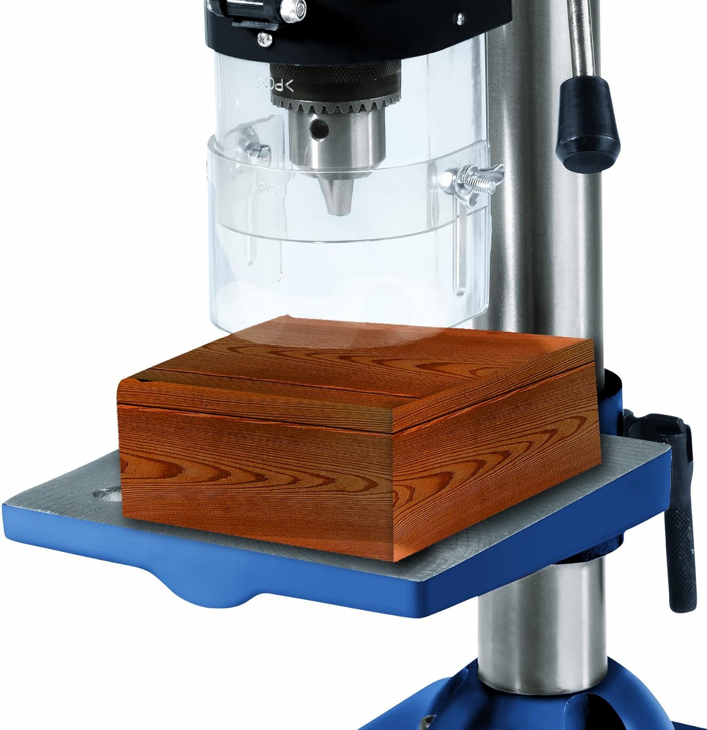
Abbildung 9: Bspample of a workpiece placed on the drill table, ready for drilling.
6. Wartung
Regelmäßige Wartung gewährleistet die Langlebigkeit und den sicheren Betrieb Ihrer Säulenbohrmaschine.
- Reinigung: After each use, clean the drill to remove dust, chips, and debris. The drill may come with a protective grease coating; remove this before first use and apply anti-corrosion maintenance as needed.
- Gurtspannung: Periodically check the drive belt tension. A loose belt can slip, reducing drilling efficiency. Adjust as described in Section 5.1.
- Spindle Play Adjustment: Over time, the spindle may develop excessive play. To adjust this:
- Fully extend the spindle by rotating the feed handles.
- Locate the black screw on the left side of the drill head, just above the chuck.
- Loosen the lock nut and then turn the black screw to reduce any excessive movement or play in the spindle.
- Once the desired adjustment is achieved, tighten the lock nut. This adjustment may need to be performed periodically.
- Schmierung: Apply light machine oil to moving parts and pivot points as necessary to ensure smooth operation.
- Electrical Cord Inspection: Überprüfen Sie das Netzkabel regelmäßig auf Beschädigungen. Ersetzen Sie es umgehend, falls es beschädigt ist.
7. Fehlerbehebung
If you encounter issues with your Einhell BT-BD 501 Pillar Drill, refer to the following common problems and solutions:
| Problem | Mögliche Ursache | Lösung |
|---|---|---|
| Bohrer startet nicht | Keine Stromversorgung | Überprüfen Sie Netzkabel, Steckdose und Sicherungsautomat. |
| Safety switch in belt compartment activated | Ensure the belt compartment cover is fully closed. A safety switch prevents operation when the cover is open. Inspect the plastic element that activates the switch for damage. | |
| Drill bit slips or stops rotating | Loose chuck jaws | Tighten chuck jaws firmly with the chuck key. |
| Lockerer Antriebsriemen | Adjust belt tension as described in Section 5.1. | |
| Übermäßige Vibration oder Wackeln | Loser Bohrer | Ensure drill bit is securely tightened in the chuck. |
| Worn or damaged drill bit | Replace with a sharp, undamaged drill bit. | |
| Excessive spindle play | Adjust spindle play as described in Section 6. |
8. Spezifikationen
Technical data for the Einhell BT-BD 501 Pillar Drill:
| Besonderheit | Spezifikation |
|---|---|
| Hersteller | Einhell |
| Modellnummer | 4250530 (BT-BD 501) |
| Leistungsaufnahme | 500 Watt |
| Bandtage | 230 Volt |
| Frequenz | 50 Hz |
| Anzahl der Geschwindigkeiten | 9 |
| Geschwindigkeitsbereich | 280 - 2,350 U/min |
| Spannfuttertyp | Geared Chuck |
| Spannfutterkapazität | 3 - 16 mm |
| Chuck Mount | B16 |
| Throat Depth (Reach) | 115 mm |
| Max. Bohrtiefe | 50 mm |
| Abmessungen des Arbeitstisches | 170 x 170 mm |
| Abmessungen der Grundplatte | 320 x 200 mm |
| Gesamthöhe | Ca. 650 mm |
| Produktabmessungen (L x B x H) | 38 x 26 x 51 cm |
| Gewicht | 17.6 kg |
| Material | Metal with rubber handles |
| Länge des Netzkabels | 3 Meter |
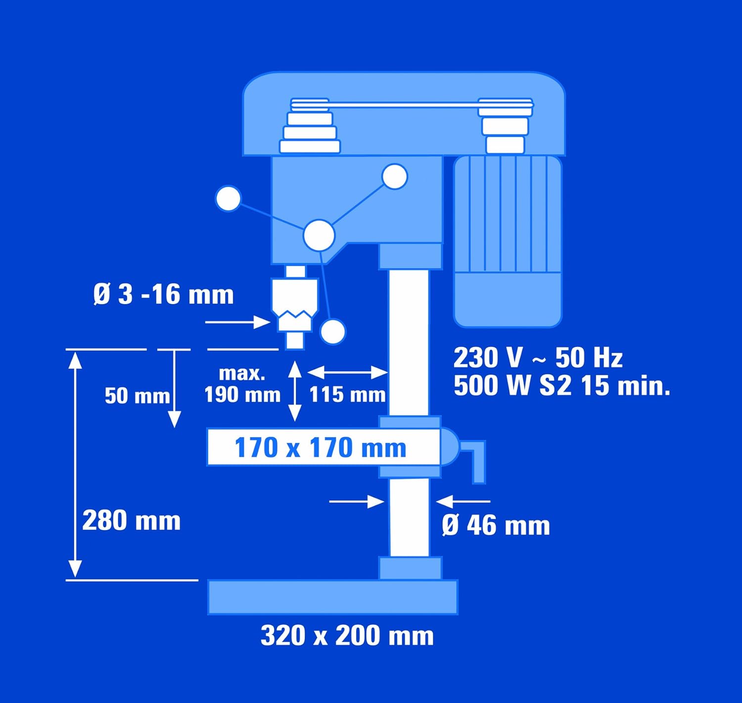
Figure 10: Technical drawing illustrating key dimensions and specifications.

Figure 11: Technical drawing showing the overall height and adjustability of the drill.
9. Garantie und Support
For warranty information, please refer to the documentation provided with your purchase or visit the official Einhell website. In case of technical issues, spare parts inquiries, or support needs, please contact your retailer or the Einhell customer service department directly. Ensure you have your model number (BT-BD 501 or 4250530) and proof of purchase available when seeking support.


