1. Einleitung
This manual provides instructions for the installation, operation, maintenance, and troubleshooting of the Juniper EX3200-24T Layer 3 Switch. The EX3200-24T is a fixed-configuration switch designed for access-layer deployments in various network environments, offering comprehensive Layer 2 and Layer 3 switching capabilities.
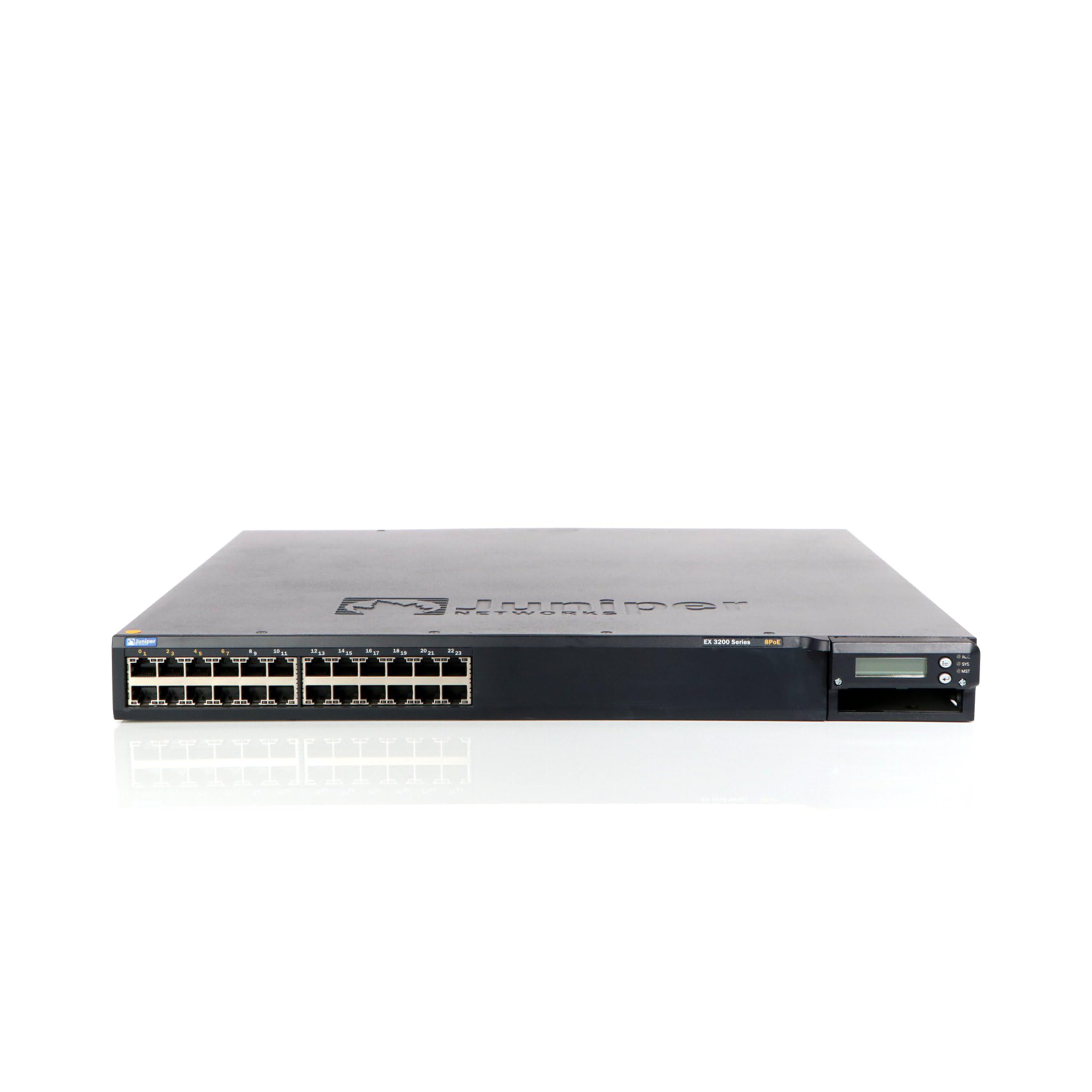
Abbildung 1: Vorderseite view of the Juniper EX3200-24T Layer 3 Switch. This image displays the 24 Ethernet ports, along with various status indicator lights and the Juniper Networks branding.
2. Einrichtung
Follow these steps to properly set up your Juniper EX3200-24T switch.
2.1 Auspacken und Prüfen
- Nehmen Sie den Schalter vorsichtig aus der Verpackung.
- Prüfen Sie den Schalter auf Anzeichen von Beschädigungen. Sollten Sie Beschädigungen feststellen, kontaktieren Sie umgehend Ihren Händler.
- Prüfen Sie, ob alle in der Packliste aufgeführten Komponenten vorhanden sind.
2.2 Rackmontage (optional)
The EX3200-24T can be mounted in a standard 19-inch equipment rack. Use the provided rack-mount kit and follow the instructions included with the kit for secure installation.
2.3 Stromversorgung anschließen
- Ensure the power switch on the rear panel of the switch is in the OFF position.
- Connect the provided AC power cord to the power inlet on the rear of the switch.
- Stecken Sie das andere Ende des Netzkabels in eine geerdete Steckdose.
2.4 Netzwerkkabel anschließen
Connect Ethernet cables from your network devices (computers, servers, other switches) to the 10/100/1000Base-T ports on the front panel of the EX3200-24T switch. Ensure cables are securely seated.
3. Bedienungsanleitung
This section outlines the basic operation of the Juniper EX3200-24T switch.
3.1 Einschalten des Switches
After connecting the power cord, flip the power switch on the rear panel to the ON position. The system status LEDs on the front panel will illuminate during the boot process.
3.2 Understanding Status LEDs
The front panel features various LEDs to indicate the operational status of the switch and its ports:
- SYS-LED: Indicates system status (e.g., green for normal operation, amber for warning, red for critical error).
- ALM-LED: Zeigt den Alarmstatus an.
- PPM LED: Indicates power supply module status.
- Port-LEDs: Each port has LEDs indicating link status and activity (e.g., green for link, blinking green for activity).
3.3 Erstkonfiguration (Konsolenzugriff)
For initial configuration, connect a console cable (RJ-45 to DB-9) from your management workstation to the console port on the switch. Use a terminal emulation program (e.g., PuTTY, Tera Term) with the following settings:
- Baudrate: 9600
- Datenbits: 8
- Parität: Keine
- Stoppbits: 1
- Flusskontrolle: Keine
Refer to the Juniper Networks documentation for detailed configuration procedures.
4. Wartung
Regular maintenance ensures optimal performance and longevity of your EX3200-24T switch.
4.1 Reinigung
- Periodically clean the exterior of the switch with a soft, dry, lint-free cloth.
- Ensure ventilation openings are free from dust and obstructions to prevent overheating. Do not use liquid or aerosol cleaners directly on the switch.
4.2 Firmware-Updates
Juniper Networks periodically releases firmware updates to improve performance, add features, and address security vulnerabilities. It is recommended to keep the switch firmware updated. Refer to the official Juniper Networks support webWebsite für die neueste Firmware und Aktualisierungsanleitungen.
4.3 Umweltaspekte
Operate the switch within its specified environmental limits (temperature, humidity) to prevent damage and ensure reliable operation. Avoid exposing the switch to direct sunlight, excessive heat, or moisture.
5. Fehlerbehebung
This section provides solutions to common issues you might encounter with your EX3200-24T switch.
5.1 Kein Strom
- Symptom: No LEDs are illuminated, and the switch does not power on.
- Aktion:
- Vergewissern Sie sich, dass das Netzkabel sowohl am Schalter als auch an der Steckdose fest angeschlossen ist.
- Stellen Sie sicher, dass sich der Netzschalter auf der Rückseite in der Position EIN befindet.
- Check the electrical outlet with another device to confirm it is functional.
- Wenn Sie eine Steckdosenleiste oder eine USV verwenden, vergewissern Sie sich, dass diese eingeschaltet ist und ordnungsgemäß funktioniert.
5.2 Keine Netzwerkverbindung
- Symptom: Devices connected to the switch cannot access the network.
- Aktion:
- Check the port LEDs on the switch for the connected device. A solid green LED indicates a link. If no link, try a different port or cable.
- Verify the network cable is securely connected at both ends (switch and device).
- Ensure the connected device's network adapter is enabled and configured correctly.
- If multiple devices are affected, check the uplink connection from the EX3200-24T to your core network.
- Consult the switch's configuration for VLANs, IP addressing, and other network settings.
5.3 System Alarm LED (ALM) is Amber/Red
- Symptom: The ALM LED is illuminated amber or red.
- Aktion:
- Log in to the switch via the console or network management interface.
- Check system logs and alarm messages for details on the specific issue.
- Common causes include power supply issues, fan failures, or high temperature.
- Address the root cause as indicated by the logs.
6. Spezifikationen
Key technical specifications for the Juniper EX3200-24T Layer 3 Switch:
| Besonderheit | Spezifikation |
|---|---|
| Marke | Juniper Networks |
| Modellnummer | EX3200-24T |
| Anzahl der Ports | 24 (16 x 10/100/1000Base-T, 8 x 10/100/1000Base-T) |
| Erweiterungssteckplatz | 1 x Expansion Slot |
| Datenübertragungsrate | 1 Gigabit pro Sekunde |
| Layer-Unterstützung | Schicht 3 |
| Artikelgewicht | 14.9 Pfund |
| Farbe | Schwarz |
| Kompatible Geräte | Desktop |
| UPC | 832938037793 |
7. Garantie und Support
7.1 Produktgarantie
The Juniper EX3200-24T Layer 3 Switch is covered by a standard manufacturer's warranty. For detailed information regarding warranty terms, duration, and coverage, please refer to the warranty card included with your product or visit the official Juniper Networks webWebsite.
7.2 Technischer Support
For technical assistance, troubleshooting beyond this manual, or to report issues, please contact Juniper Networks technical support. Support resources, including documentation, FAQs, and contact information, are available on the official Juniper Networks support portal: