Einführung
This manual provides comprehensive instructions for the installation, operation, and maintenance of your Stinger SPD514 PRO Series Power or Ground Distribution Block. Designed for high-current automotive audio systems, this distribution block efficiently manages power or ground connections, ensuring optimal performance and safety. Please read this manual thoroughly before installation to ensure correct usage and to prevent damage to the product or your vehicle's electrical system.
Wichtige Sicherheitsinformationen
- Always disconnect the vehicle's battery before installing any electrical components.
- Stellen Sie sicher, dass alle Verbindungen sicher und ordnungsgemäß isoliert sind, um Kurzschlüsse zu vermeiden.
- Use appropriate wire gauges as specified for your system's current draw.
- Install the distribution block in a dry location, away from excessive heat or moisture.
- Ziehen Sie einen Fachmann zu Rate, wenn Sie sich bei irgendeinem Teil des Installationsprozesses unsicher sind.
- This product is designed for 12-volt automotive applications only.
WARNUNG: Dieses Produkt enthält Chemikalien, von denen der Staat Kalifornien weiß, dass sie Krebs und Geburtsfehler oder andere Fortpflanzungsschäden verursachen. Weitere Informationen finden Sie unter www.P65Warnings.ca.gov.
Packungsinhalt
Vergewissern Sie sich vor Beginn der Installation, dass alle Teile vorhanden sind:
- Stinger SPD514 PRO Series Power or Ground Distribution Block
- Protective Clear Cover
- Befestigungsmaterial (Schrauben)

Image: Stinger SPD514 Distribution Block in its retail packaging, showing the product and model number.
Setup und Installation
The Stinger SPD514 is designed to distribute power or ground from a main input cable to multiple output cables. Follow these steps for proper installation:
1. Wählen Sie einen Montageort.
Select a secure, dry, and easily accessible location for the distribution block. Ensure it is away from moving parts, excessive heat, and moisture. The block can be surface-mounted using the provided screws.
2. Prepare Wiring
- Eingangsdrähte: The SPD514 accepts two 1/0 gauge input wires. Strip approximately 1/2 inch (12-15mm) of insulation from the ends of your main power or ground cables.
- Ausgangsdrähte: The block provides four output terminals, compatible with 4 or 8 gauge wires. Strip approximately 1/2 inch (12-15mm) of insulation from the ends of your amplifier or accessory power/ground cables.

Bild: Draufsicht view of the Stinger SPD514 distribution block with its clear protective cover, showing the two large input terminals and four smaller output terminals.
3. Connect Input Wires
- Loosen the set screws for the two large input terminals on the distribution block.
- Insert the stripped ends of your 1/0 gauge main power or ground cables into the respective input terminals.
- Tighten the set screws firmly to ensure a secure connection. Do not overtighten.
4. Connect Output Wires
- Loosen the set screws for the four smaller output terminals.
- Insert the stripped ends of your 4 or 8 gauge power or ground cables into the output terminals.
- Tighten the set screws firmly. Verify that all connections are snug and that no loose strands of wire are exposed.
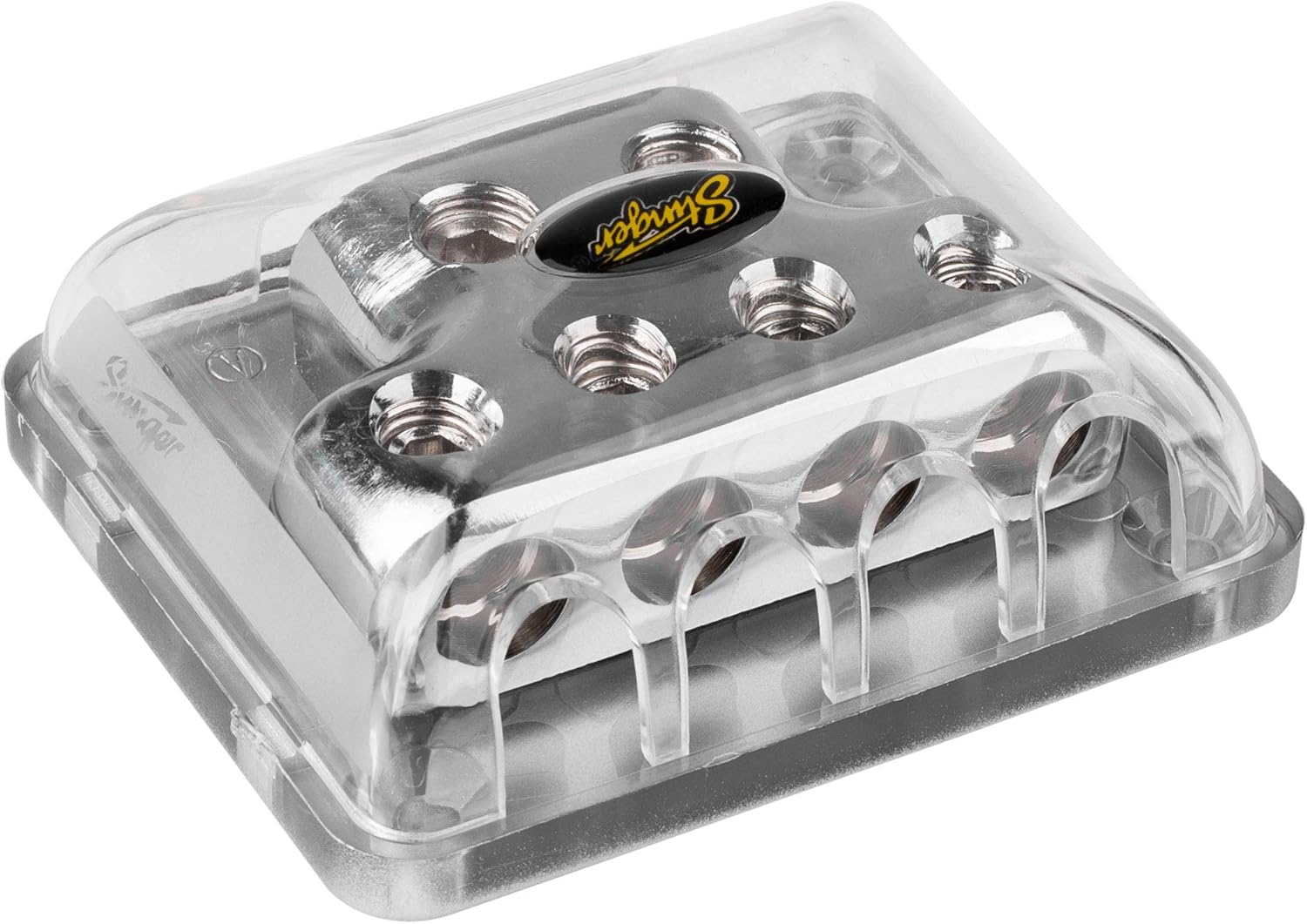
Abbildung: Seite view of the Stinger SPD514 distribution block, highlighting the four output terminals where smaller gauge wires are connected.
5. Secure the Protective Cover
Once all wiring is complete and connections are secure, place the clear protective cover over the distribution block. This cover helps prevent accidental short circuits and protects the terminals from environmental elements.
Betrieb
The Stinger SPD514 is a passive component designed to distribute electrical current. It does not require active operation. Once properly installed, it functions by providing a common connection point for multiple power or ground wires, ensuring efficient current flow to connected devices. Always ensure that the total current draw of all connected devices does not exceed the capacity of your main input wire and the distribution block itself.
Wartung
- Regelmäßige Inspektion: Periodically inspect the distribution block and all connected wires for signs of corrosion, loose connections, or damage.
- Reinigung: If necessary, gently clean the exterior of the block with a dry, soft cloth. Do not use abrasive cleaners or solvents. Ensure the protective cover is always in place.
- Verbindungsintegrität: Re-tighten set screws if any connections appear loose. Loose connections can lead to resistance, heat buildup, and potential system failure.
Fehlerbehebung
If you experience issues with your electrical system after installing the distribution block, consider the following:
- Keine Stromversorgung für Geräte:
- Check all input and output wire connections for tightness.
- Verify that the main power/ground cable is properly connected to the vehicle's battery/chassis.
- Ensure any inline fuses (not part of this product) are intact and not blown.
- Excessive Heat at Block or Wires:
- This indicates high resistance or excessive current draw.
- Check all connections for looseness or corrosion.
- Ensure the wire gauges used are appropriate for the current demands of your system. Undersized wires can cause heat.
- Verify that the total current draw does not exceed the block's capacity.
- Intermittierende Leistung:
- Inspect for loose or corroded connections at the distribution block, battery, and connected devices.
- Check for damaged insulation on wires that could lead to intermittent shorts.
If problems persist, consult a qualified automotive audio technician.
Technische Daten
| Besonderheit | Detail |
|---|---|
| Modellnummer | SPD514 |
| Marke | STINGER |
| Eingangsanschlüsse | Two (2) 1/0 Gauge |
| Ausgangsanschlüsse | Four (4) 4 or 8 Gauge |
| Steckertyp | Stellschraube |
| Material | Brass with ShocKrome Finish |
| Bandtage Kompatibilität | 12 Volt (DC) |
| Abmessungen (L x B x H) | 5.9 x 1.5 x 4 Zoll |
| Artikelgewicht | 7.7 Unzen |
| Montagetyp | Oberflächenmontage |
Garantie und Support
For information regarding warranty coverage, technical support, or replacement parts, please refer to the official STINGER webBesuchen Sie die Website oder kontaktieren Sie direkt den Kundenservice. Bewahren Sie Ihren Kaufbeleg als Kaufnachweis für eventuelle Garantieansprüche auf.
STINGER Offiziell WebWebsite: www.stinger.com (Hinweis: Dies ist ein Platzhalter. URLBitte überprüfen Sie die Angaben des tatsächlichen Herstellers. webWebsite für Unterstützung.)
Rechtliche Hinweise
Warnung zu Proposition 65: Dieses Produkt enthält Chemikalien, von denen der Staat Kalifornien weiß, dass sie Krebs und Geburtsfehler oder andere Fortpflanzungsschäden verursachen. Weitere Informationen finden Sie unter www.P65Warnings.ca.gov.


