1. Einleitung
The Velleman DVM810 is a compact and economical 3 1/2 digit digital multimeter designed for measuring DC and AC voltages, DC currents, resistance, and for performing diode and transistor (hFE) tests. It features overload protection and automatic polarity indication, making it suitable for hobbyists, field use, and workshops. This manual provides essential information for the safe and effective operation of your DVM810 multimeter.
2. Produktmerkmale
- Automatic polarity indication
- Bandtage measurements: AC 500V and DC 500V maximum
- Current measurements: DC 10A maximum (0.2A fused, 10A unfused)
- Resistance measurements: Up to 2MΩ
- Diode and transistor (hFE) test functions
- Überlastschutz
- Compact design with 3 1/2 digit LCD display
3. Packungsinhalt
Bitte überprüfen Sie den Packungsinhalt, um sicherzustellen, dass alle Artikel vorhanden sind:
- Velleman DVM810 Digitalmultimeter
- Messleitungen (eine rote, eine schwarze)
- Bedienungsanleitung
4. Wichtige Sicherheitshinweise
Lesen Sie vor der Verwendung dieses Produkts alle Sicherheitshinweise und Anweisungen sorgfältig durch. Die Nichtbeachtung dieser Anweisungen kann zu Stromschlag, Brand oder schweren Verletzungen führen.
- Vor jeder Messung sollte sichergestellt sein, dass das Multimeter auf die richtige Funktion und den richtigen Messbereich eingestellt ist.
- Never exceed the maximum input limits for any range. The maximum voltage for AC/DC is 500V.
- Versuchen Sie nicht, den Strom in Stromkreisen mit Spannung zu messen.tagEs überschreitet 250 V.
- Inspect test leads for damaged insulation or exposed metal before each use. Replace damaged leads immediately.
- Verwenden Sie das Multimeter nicht, wenn es beschädigt erscheint oder das Gehäuse geöffnet ist.
- Exercise extreme caution when working with live circuits. Use appropriate personal protective equipment.
- Trennen Sie immer die Stromzufuhr zum Stromkreis und entladen Sie die Hochspannungsbatterie.tage capacitors before measuring resistance or performing diode/transistor tests.
- Tauschen Sie die Batterie aus, sobald die Anzeige für niedrigen Batteriestand erscheint, um genaue Messwerte zu gewährleisten.
5. Produktüberschreitungview
Familiarize yourself with the components of your Velleman DVM810 multimeter:
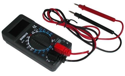
Figure 1: Velleman DVM810 Digital Multimeter. This image displays the front view of the compact multimeter, highlighting its liquid crystal display (LCD), the central rotary function switch, and the input jacks for test leads at the bottom.
- LCD Anzeige: Shows measurement readings, units, and polarity.
- Drehschalter: Dient zur Auswahl der gewünschten Messfunktion und des Messbereichs.
- Eingangsbuchsen:
- COM-Buchse: Gemeinsamer (negativer) Eingang für alle Messungen. Schließen Sie hier die schwarze Messleitung an.
- VΩmA-Buchse: Positiver Input für Voltage, resistance, and current measurements up to 200mA. Connect the red test lead here.
- 10A-Buchse: Positive input for high current measurements (up to 10A). Connect the red test lead here for 10A measurements.
- Messleitungen: Red and black leads used to connect the multimeter to the circuit under test.
6. Einrichtung
6.1 Einlegen der Batterie
The DVM810 multimeter requires a 9V battery (not always included). To install or replace the battery:
- Ensure the multimeter is turned OFF (rotary switch set to OFF).
- Suchen Sie die Abdeckung des Batteriefachs auf der Rückseite des Geräts.
- Entfernen Sie die Schraube(n), mit der/denen die Abdeckung befestigt ist/sind, und heben Sie diese vorsichtig ab.
- Schließen Sie eine neue 9V-Batterie an den Batterieclip an und achten Sie dabei auf die richtige Polarität.
- Setzen Sie die Batterie in das Batteriefach ein und bringen Sie den Deckel wieder an. Befestigen Sie ihn anschließend mit der/den Schraube(n).
6.2 Anschließen der Testleitungen
Schließen Sie die Messleitungen stets korrekt an, um genaue und sichere Messungen zu gewährleisten:
- Stecken Sie die schwarze Messleitung in den COM (gemeinsame) Buchse.
- Für die meisten Messungen (Vol.tage, resistance, diode, hFE, and current up to 200mA), insert the red test lead into the VΩmA Jack.
- Für Hochstrommessungen (bis zu 10 A) führen Sie die rote Messleitung in den/die/das ein. 10 A Jack.
7. Bedienungsanleitung
Before making any measurement, ensure the test leads are correctly connected and the rotary switch is set to the appropriate function and range.
7.1 Messen der Gleichspannungtage (V=)
- Stecken Sie die rote Leitung in die VΩmA jack and the black lead into the COM Jack.
- Stellen Sie den Drehschalter auf die gewünschte Gleichstromstärke ein.tage (V=) range. Start with the highest range if the voltage ist unbekannt.
- Connect the test leads across the component or circuit to be measured (in parallel).
- Lesen Sie den Bandtage value on the LCD display. The display will show the correct polarity.
7.2 Messen der Wechselspannungtage (V~)
- Stecken Sie die rote Leitung in die VΩmA jack and the black lead into the COM Jack.
- Stellen Sie den Drehschalter auf die gewünschte Wechselstromspannung ein.tage (V~) range. Start with the highest range if the voltage ist unbekannt.
- Connect the test leads across the component or circuit to be measured (in parallel).
- Lesen Sie den Bandtage-Wert auf dem LCD-Display.
7.3 Messung des Gleichstroms (A=)
Caution: Never connect the multimeter in parallel with a voltagDie Stromquelle beim Messen des Stroms nicht berühren, da dies die Sicherung durchbrennen oder das Messgerät beschädigen kann.
- Determine the expected current. For currents up to 200mA, insert the red lead into the VΩmA jack. For currents up to 10A, insert the red lead into the 10 A jack. Always insert the black lead into the COM Jack.
- Set the rotary switch to the appropriate DC Current (A=) range. Start with the highest range if the current is unknown.
- Turn off power to the circuit. Open the circuit where the current is to be measured.
- Schließen Sie das Multimeter in Reihe mit dem Stromkreis an.
- Restore power to the circuit and read the current value on the LCD display.
7.4 Widerstandsmessung (Ω)
Caution: Ensure the circuit is completely de-energized and all capacitors are discharged before measuring resistance.
- Stecken Sie die rote Leitung in die VΩmA jack and the black lead into the COM Jack.
- Set the rotary switch to the desired Resistance (Ω) range. Start with a higher range if the resistance is unknown.
- Schließen Sie die Messleitungen an das zu messende Bauteil an.
- Lesen Sie den Widerstandswert auf dem LCD-Display ab.
7.5 Diodentest
Caution: Ensure the diode is disconnected from the circuit or the circuit is de-energized before testing.
- Stecken Sie die rote Leitung in die VΩmA jack and the black lead into the COM Jack.
- Set the rotary switch to the Diode symbol (→|).
- Schließen Sie die rote Leitung an die Anode und die schwarze Leitung an die Kathode der Diode an. Das Display zeigt die Durchlassspannung an.tage-Spannungsabfall (typischerweise 0.5 V bis 0.8 V für Siliziumdioden).
- Reverse the leads. The display should show 'OL' (Overload) for a good diode. If it shows a reading in both directions or 'OL' in both directions, the diode may be faulty.
7.6 Transistor (hFE) Test
Caution: Ensure the transistor is disconnected from the circuit before testing.
- Stecken Sie die rote Leitung in die VΩmA jack and the black lead into the COM Jack.
- Stellen Sie den Drehschalter auf die Position hFE.
- Identify if the transistor is NPN or PNP. Insert the transistor's emitter, base, and collector leads into the corresponding holes in the hFE socket on the multimeter.
- Read the hFE (DC current gain) value on the LCD display.
8. Spezifikationen
| Parameter | Wert |
|---|---|
| Marke | Velleman |
| Modellnummer | DVM810 |
| Messtyp | Multimeter |
| DC-Voltage Reichweite | Bis zu 500V |
| AC-Lautstärketage Reichweite | Bis zu 500V |
| Gleichstrombereich | Up to 10A (0.2A fused, 10A unfused) |
| Widerstandsbereich | Bis zu 2 MΩ |
| Diodentest | Ja |
| Transistortest (hFE) | Ja |
| Anzeige | 3 1/2 Digit LCD |
| Stromquelle | 9V-Batterie (nicht im Lieferumfang enthalten) |
| Maße | Ungefähr 3.70" x 1.81" x 1.03" |
| Artikelgewicht | Ungefähr 3.2 Unzen (0.2 Pfund) |
| UPC | 836479002272 |
9. Wartung
9.1 Batteriewechsel
When the low battery indicator appears on the LCD, replace the 9V battery as described in Section 6.1. A weak battery can lead to inaccurate readings.
9.2 Reinigung
Um das Multimeter zu reinigen, wischen Sie das Gehäuse mit einem feuchten Tuch ab.amp Reinigen Sie das Gerät mit einem Tuch und einem milden Reinigungsmittel. Verwenden Sie keine Scheuermittel oder Lösungsmittel. Stellen Sie sicher, dass das Gerät vor Gebrauch vollständig trocken ist.
9.3 Prüfung der Testleitungen
Regularly inspect the test leads for any signs of damage, such as cracked insulation, exposed wires, or loose connections. Replace damaged leads immediately to prevent electric shock hazards.
10. Fehlerbehebung
- Keine oder nur schwache Anzeige: Überprüfen Sie die Batterie. Tauschen Sie sie gegebenenfalls aus.
- Falsche Messwerte:
- Stellen Sie sicher, dass der Drehschalter auf die richtige Funktion und den richtigen Bereich eingestellt ist.
- Überprüfen Sie die Batterieladungtage; replace if low.
- Stellen Sie sicher, dass die Messleitungen ordnungsgemäß angeschlossen und nicht beschädigt sind.
- Für Widerstandsmessungen muss sichergestellt werden, dass der Stromkreis stromlos ist.
- 'OL' (Überlastung) wird angezeigt: The measured value exceeds the selected range. Select a higher range or ensure the circuit is within the meter's capabilities.
- Fuse blown (during current measurement): If the meter stops measuring current, the internal fuse may have blown. Refer to a qualified technician for fuse replacement.
11. Garantie und Support
Warranty information for the Velleman DVM810 Digital Multimeter is typically provided with your purchase documentation or can be found on the official Velleman website. For technical support, service, or further inquiries, please refer to the contact information provided by your retailer or the manufacturer's official support channels.


