1. Einleitung
This manual provides essential information for the safe and efficient installation, operation, and maintenance of the Uponor Thermal Actuator ST230, 230V, Model 1013006. Please read these instructions carefully before proceeding with installation or use. Retain this manual for future reference.
2. Produktüberschreitungview
The Uponor Thermal Actuator ST230, 230V, Model 1013006 is designed for controlling the return valves on Uponor Vario S manifolds in underfloor heating systems. It operates on 230 Volts and features a screw connection IG M 30 x 1.5, a stroke indicator, and a 1.0-meter connection cable with wire end ferrules. The unit is splash-proof with an IP54 rating and is CE and RoHS certified.

Abbildung 2.1: Uponor Thermal Actuator ST230, 230V, Model 1013006. This image shows the blue housing of the actuator with the Uponor logo and the grey screw connection base.
3. Sicherheitshinweise
- Installation and electrical connections must be performed by a qualified electrician or authorized personnel in accordance with local regulations and standards.
- Ensure the main power supply is disconnected before performing any installation, maintenance, or troubleshooting.
- Das Aktuatorgehäuse darf nicht geöffnet werden. Es enthält keine vom Benutzer wartbaren Teile.
- Protect the device from direct water spray or immersion, despite its splash-proof rating.
- Use only genuine Uponor components and accessories.
4. Einrichtung und Installation
The thermal actuator is designed for easy mounting on Uponor Vario S manifold return valves. Follow these steps for proper installation:
- Ensure the heating system is depressurized and the manifold valves are in the correct position for actuator mounting.
- Carefully screw the actuator onto the valve connection (IG M 30 x 1.5) by hand until it is securely fastened. Do not overtighten.
- Connect the 230V electrical cable to the appropriate control unit or thermostat terminals. The cable is 0.75 mm² x 1.0 m and comes with wire end ferrules for secure connection.
- Verify all connections are secure and correctly wired according to the system's electrical diagram.
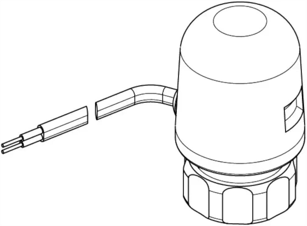
Abbildung 4.1: Diagram showing the Uponor Thermal Actuator with its integrated connection cable. This illustrates the actuator's form factor and cable exit point.

Abbildung 4.2: Dimensional drawing of the Uponor Thermal Actuator, indicating key measurements (do, h, G) for installation planning. 'do' represents the outer diameter, 'h' the height, and 'G' the thread size.
5. Bedienungsanleitung
The Uponor Thermal Actuator operates automatically in conjunction with a room thermostat or heating control system. When the control system signals a demand for heat, the actuator receives power, causing its internal element to expand and open the valve. When the heat demand is met, power is removed, and the actuator cools, closing the valve.
- Stroke Indicator: The actuator is equipped with a stroke indicator, typically a small pin or window, which visually confirms the valve's open or closed position. Observe this indicator to verify proper operation.
- Erstinbetriebnahme: After installation and power-up, allow a short period for the actuator to respond to the control signal and fully open or close the valve.
6. Wartung
The Uponor Thermal Actuator ST230, 230V, Model 1013006 is designed for maintenance-free operation. No regular servicing or lubrication is required.
- Keep the exterior of the actuator clean and free from dust or debris. Use a soft, dry cloth for cleaning.
- Keine Scheuer- oder Lösungsmittel verwenden.
- Periodically check the electrical connections for any signs of wear or damage.
7. Fehlerbehebung
If the thermal actuator is not functioning as expected, consider the following:
- Actuator not opening/closing:
- Check if the control system (thermostat) is calling for heat.
- Verify that the actuator is receiving 230V power.
- Ensure electrical connections are secure and correct.
- Confirm the actuator is correctly screwed onto the valve.
- No visible movement of stroke indicator:
- Allow sufficient time for the actuator to react (thermal actuators have a delay).
- Check power supply and control signal.
If issues persist after checking these points, contact qualified service personnel.
8. Spezifikationen

Abbildung 8.1: Technical data sheet for the Uponor Thermal Actuator ST230, 230V, Model 1013006, providing detailed specifications and contact information.
| Spezifikation | Wert |
|---|---|
| Marke | Uponor |
| Modellnummer | 1013006 |
| Hersteller | Uponor |
| Produktabmessungen (L x B x H) | 5 x 5 x 7.5 cm |
| Gewicht | 120 Gramm |
| Bandtage | 230 Volt |
| Maximale Lautstärketage | 230 Volt |
| Steckertyp | Spaten |
| Kontaktmaterial | Edelstahl |
| Isoliermaterial | Polyolefin |
| Terminaltyp | Spade Terminal |
| Konforme Spezifikationen | CE, RoHS |
| Ursprungsland | Deutschland |
| Internationaler Artikelcode (EAN) | 04021598002937 |
| Verbindungskabel | 0.75 mm² x 1.0 m, without plug, with wire end ferrules |
| Schutzklasse | IP54 (spritzwassergeschützt) |
| Ventilanschluss | Screw connection IG M 30 x 1.5 |
| Besonderheit | Hubanzeige |
9. Garantie und Support
Uponor products are manufactured to high-quality standards. For specific warranty terms and conditions, please refer to the documentation provided with your purchase or contact Uponor directly. Information regarding spare parts availability is not provided in the product specifications.
Kontaktinformationen:
Uponor GmbH
Industriestraße 56
97437 Hassfurt
Deutschland
Telefon: +4932210090856
E-Mail: Kundenservice@uponor.com
WebWebsite: www.uponor.com/de-de


