1. Produktüberschreitungview
The WAGO 8001-001/K010-9890/0000-0400 is an industrial interface module designed for reliable electrical connections in various applications, including prototyping boards and semiconductor product interfaces. This module facilitates secure and organized wiring within industrial electrical systems, ensuring efficient signal and power distribution.
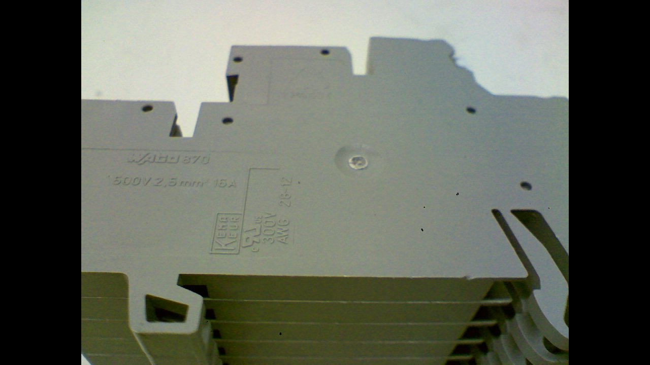
Abbildung 1: Nahaufnahme view of the WAGO 8001-001/K010-9890/0000-0400 industrial interface module, displaying its model number and electrical specifications such as 500V/2.5mm² 16A. This image highlights the detailed markings on the side of the module.
2. Sicherheitshinweise
Please read and understand all safety instructions before installing, operating, or maintaining this product. Failure to follow these instructions may result in electric shock, fire, serious injury, or death.
- Qualifiziertes Personal: Installation und Wartung dürfen nur von qualifiziertem und autorisiertem Personal durchgeführt werden.
- Stromabschaltung: Always disconnect power to the circuit before working on the module or making any connections. Verify that power is off using appropriate testing equipment.
- Richtiges Werkzeug: Use only insulated tools suitable for electrical work.
- Umgebungsbedingungen: Ensure the operating environment is free from excessive moisture, dust, corrosive gases, and extreme temperatures.
- Wiring Standards: Adhere to all local and national electrical codes and standards.
3. Einrichtung
Proper setup is crucial for the reliable operation of the WAGO interface module.
3.1 Montage
- Select a suitable mounting location within the control cabinet or enclosure, ensuring adequate space for wiring and ventilation.
- Mount the module securely onto a DIN rail using its integrated mounting mechanism. Ensure it clicks firmly into place.
- Verify that the module is stable and will not vibrate loose during operation.
3.2 Kabelverbindungen
The module features multiple connection points for various signals and power lines.
- Identify the appropriate terminals for your application (e.g., input, output, power, ground). Refer to your system's wiring diagram.
- Strip wire insulation to the recommended length (typically 8-10 mm) to ensure proper contact without exposed conductors.
- Insert the stripped wire into the designated terminal opening.
- Betätigen Sie den Clamping mechanism (e.g., push-in or lever) to secure the wire firmly. Gently pull on the wire to confirm it is properly seated and cannot be easily dislodged.
- Repeat for all necessary connections, ensuring correct polarity and signal assignment.

Abbildung 2: Seite view of the WAGO 8001-001/K010-9890/0000-0400 module, illustrating its multi-level design which allows for high-density wiring in a compact form factor. This view helps in understanding the physical dimensions and structure for mounting.

Abbildung 3: Von oben nach unten view of the WAGO 8001-001/K010-9890/0000-0400 module, providing a clear perspective of the numbered connection points. This view is essential for accurate wiring and identification of individual terminals.
4. Bedienungsanleitung
Once properly installed and wired, the WAGO interface module operates passively, providing reliable electrical connections. Its primary function is to serve as a robust and organized interface for signals and power within an industrial control system.
- Power Application: After all connections are verified, apply power to the circuit.
- Signalfluss: Signals and power will pass through the module according to your system's design.
- Überwachung: Monitor connected devices for proper operation. The module itself does not require active control or programming.
5. Wartung
The WAGO interface module is designed for minimal maintenance. Regular inspections are recommended to ensure continued reliable operation.
- Sichtprüfung: Überprüfen Sie das Modul regelmäßig auf Anzeichen von physischen Beschädigungen, Verfärbungen oder lockeren Verbindungen.
- Verbindungsintegrität: Ensure all wires remain securely fastened in their terminals. Re-tighten or re-insert any loose connections after disconnecting power.
- Reinigung: If necessary, gently clean the module with a dry, lint-free cloth. Do not use solvents or abrasive cleaners. Ensure power is disconnected before cleaning.
- Umweltcheck: Verify that the operating environment continues to meet the specified conditions (temperature, humidity, absence of contaminants).
6. Fehlerbehebung
Sollten Probleme auftreten, beachten Sie bitte die folgenden Schritte zur Fehlerbehebung:
- Kein Signal/Strom:
- Prüfen Sie, ob die Stromversorgung des Stromkreises gewährleistet ist.
- Check all connections to and from the module for proper seating and continuity.
- Ensure correct wiring according to your system diagram.
- Intermittierende Verbindung:
- Prüfen Sie auf lose Drähte oder beschädigte Isolierung.
- Ensure wires are stripped to the correct length and fully inserted into the terminals.
- Physischer Schaden:
- If the module shows signs of physical damage (e.g., cracks, burns), it should be replaced immediately.
If problems persist after following these steps, consult a qualified electrician or contact WAGO technical support.
7. Spezifikationen
| Attribut | Wert |
|---|---|
| Modellnummer | 8001-001/K010-9890/0000-0400 |
| Hersteller | WAGO |
| ASIN | B0115HA4E |
| Datum der ersten Verfügbarkeit | 7. Juli 2015 |
| Typische Anwendung | Industrial Electrical, Semiconductor Interfaces, Prototyping |
8. Garantie und Support
For specific warranty information regarding the WAGO 8001-001/K010-9890/0000-0400 module, please refer to the official WAGO website or contact your authorized WAGO distributor. WAGO products are typically covered by a manufacturer's warranty against defects in materials and workmanship.
For technical support, product inquiries, or assistance with troubleshooting, please visit the official WAGO website or contact their customer service department. You can often find detailed product documentation, FAQs, and contact information on their site.
WAGO Official WebWebsite: www.wago.com


