1. Einleitung
This manual provides essential information for the safe and efficient operation of your Cotek SP-3000-112 High Frequency Pure Sine Wave Inverter. This device converts 12V DC power from batteries into 120V AC power, suitable for a wide range of electronic appliances. Please read this manual thoroughly before installation and use, and retain it for future reference.
2. Sicherheitshinweise
Failure to follow these safety instructions may result in electric shock, fire, serious injury, or death. Always exercise caution when working with electrical equipment.
- Lies alle Anweisungen: Before operating the inverter, read all instructions and cautionary markings on the inverter, the batteries, and all appropriate sections of this manual.
- Qualifiziertes Personal: Installation and servicing should be performed by qualified personnel familiar with batteries and inverters.
- Belüftung: Ensure adequate ventilation around the inverter. Do not install in a zero-clearance compartment.
- Wasser vermeiden: Do not expose the inverter to rain, snow, spray, or bilge water.
- Richtige Erdung: Der Wechselrichter muss ordnungsgemäß geerdet sein.
- Batteriesicherheit: Work near lead-acid batteries is dangerous. Batteries generate explosive gases during normal operation. Ensure proper ventilation and wear appropriate personal protective equipment.
- Stromversorgung trennen: Always disconnect the battery supply before performing any maintenance or troubleshooting.
- Richtig Voltage: Stellen Sie sicher, dass die DC-Eingangsspannungtage matches the inverter's specifications (12VDC for this model).


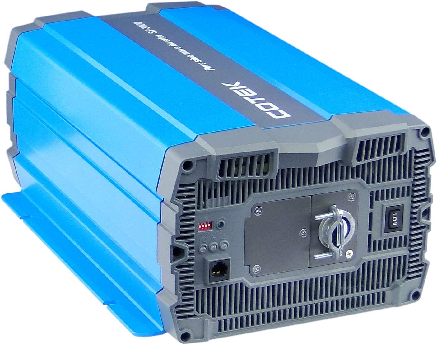
3. Produktüberschreitungview
3.1 Hauptmerkmale
- Reiner Sinuswellenausgang für empfindliche Elektronik.
- Ein-/Ausschaltfunktion per Fernbedienung (grüner Anschluss).
- Ein- und Ausgänge sind für erhöhte Sicherheit vollständig voneinander getrennt.
- Temperatur- und lastgesteuerter Lüfter für optimale Leistung.
- Benutzerfreundliche Oberfläche mit 3-farbigen LED-Statusanzeigen.
- Multiple protection features: Reverse Polarity (Fuse), Under Voltage / Über Voltage, Output Protection (Short Circuit / Overload / Over Temperature).
- E-13 / UL / CE / FCC approved.
3.2 Wechselrichterkomponenten

4. Einrichtung und Installation
Proper installation is crucial for the safe and efficient operation of your inverter. Refer to local electrical codes and standards.
4.1 Platzierung
- Installieren Sie den Wechselrichter an einem trockenen, gut belüfteten Ort, fern von direkter Sonneneinstrahlung, Wärmequellen und brennbaren Materialien.
- Ensure sufficient clearance around the inverter for proper airflow, especially around the cooling fan vents.
- Montieren Sie den Wechselrichter sicher auf einer stabilen, nicht brennbaren Oberfläche.
- Avoid areas where dust, moisture, or corrosive fumes are present.
4.2 Verkabelung
All wiring must comply with applicable electrical codes and be performed by a qualified electrician.
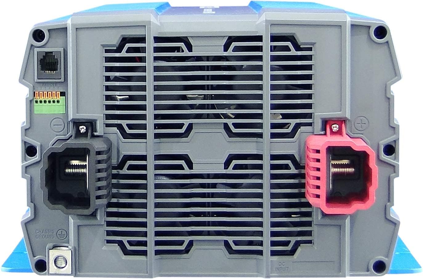
- Erdung: Connect the inverter's chassis ground terminal to a reliable earth ground using appropriate gauge wire.
- DC-Eingangsanschluss:
- Stellen Sie sicher, dass die Batteriebank spannungsfrei ist.tage ist 12 V DC.
- Use appropriately sized cables for the DC input to minimize voltage drop and ensure safety. Refer to cable sizing charts based on current and distance.
- Connect the positive (+) terminal of the battery bank to the red (+) terminal on the inverter.
- Connect the negative (-) terminal of the battery bank to the black (-) terminal on the inverter.
- Install a DC-rated fuse or circuit breaker between the battery bank and the inverter's positive terminal, as close to the battery as possible.
- AC-Ausgangsanschluss:
- Connect your AC loads to the hardwire AC output terminal block.
- Ensure the total load does not exceed the inverter's continuous power rating (3000W).
- Fernbedienung (optional): Connect the remote control unit to the RJ45 port or use the green terminal for external ON/OFF control if desired.
5. Bedienungsanleitung
5.1 Ein-/Ausschalten
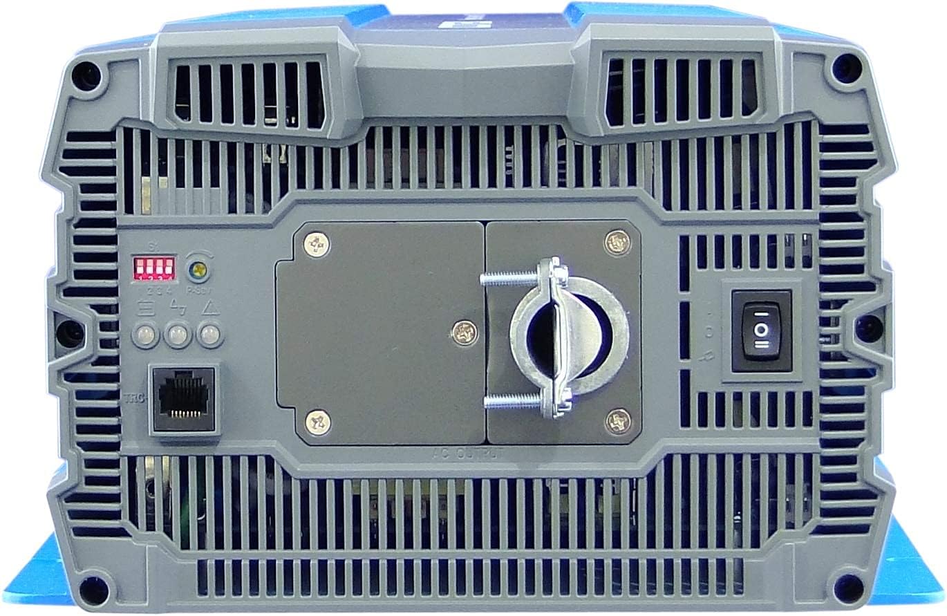
- So schalten Sie das Gerät ein: Ensure all DC and AC connections are secure. Flip the main power switch on the inverter's rear panel to the 'ON' position. The Power LED indicator should illuminate.
- So schalten Sie das Gerät aus: Disconnect all AC loads from the inverter. Flip the main power switch to the 'OFF' position.
5.2 LED-Anzeigen
The inverter features 3-color LED status indicators on the control panel (refer to Figure 4) to provide operational feedback:
- Grüne LED: Indicates normal operation and power output.
- Gelbe LED: Indicates a warning condition, such as low battery voltage or high temperature. The inverter may continue to operate but requires attention.
- Rote LED: Indicates a fault condition, such as overload, short circuit, or severe over/under voltage. The inverter will shut down to protect itself and connected devices.
5.3 DIP-Schaltereinstellungen
The DIP switches on the control panel allow for customization of certain inverter parameters, such as output voltage, frequency, and power saving mode. Refer to the detailed specifications table (Figure 5) or the product datasheet for specific configurations. Always adjust DIP switches when the inverter is powered off.
6. Wartung
Regelmäßige Wartung gewährleistet die Langlebigkeit und den zuverlässigen Betrieb Ihres Wechselrichters.
- Reinigung: Reinigen Sie die Außenseite des Wechselrichters regelmäßig mit einem trockenen Tuch. Achten Sie darauf, dass die Lüftungsöffnungen frei von Staub und Schmutz sind. Verwenden Sie keine flüssigen Reinigungsmittel.
- Verbindungen: Regularly check all electrical connections (DC input, AC output, ground) for tightness and corrosion. Loose connections can cause overheating and poor performance.
- Batterieinspektion: Inspect batteries for signs of damage, corrosion, or electrolyte leakage. Ensure battery terminals are clean and tight.
- Umfeld: Vergewissern Sie sich, dass die Betriebsumgebung innerhalb der vorgegebenen Temperatur- und Feuchtigkeitsbereiche bleibt.
7. Fehlerbehebung
Dieser Abschnitt bietet Lösungen für häufig auftretende Probleme. Sollte das Problem weiterhin bestehen, wenden Sie sich bitte an den Kundensupport.
| Problem | Mögliche Ursache | Lösung |
|---|---|---|
| Der Wechselrichter schaltet sich nicht ein. | No DC input power; Loose battery connections; Blown DC fuse/breaker; Inverter switch OFF. | Überprüfen Sie die Batterieladungtage; Tighten connections; Replace fuse/reset breaker; Turn inverter switch ON. |
| Kein AC-Ausgang. | Overload; Short circuit; Over-temperature shutdown; Low/High DC input voltage. | Reduce AC load; Check for short circuits in wiring/appliances; Allow inverter to cool; Check battery voltage. |
| Yellow LED illuminated. | Niedrige Batterieladungtage warning; High temperature warning. | Recharge batteries; Ensure adequate ventilation, reduce load. |
| Red LED illuminated / Inverter shut down. | Overload; Short circuit; Over-temperature; Under/Over voltage. | Identify and correct the fault (e.g., reduce load, fix short, allow cooling, check battery voltage), then restart the inverter. |
| Der Lüfter läuft ständig oder ist sehr laut. | Hohe Innentemperatur aufgrund hoher Belastung oder mangelhafter Belüftung. | Reduce load; Improve ventilation around the inverter. |
8. Spezifikationen
The following table outlines the technical specifications for the Cotek SP-3000 Series Pure Sine Wave Inverter, specifically for the SP-3000-112 model.

| Kategorie | Parameter | SP-3000-112 |
|---|---|---|
| Ausgabe | AC-Lautstärketage | 100 / 110 / 115 / 120 VAC ±5 % |
| Nennleistung | 3000 W | |
| Surge Power (1 Sec.) | 6000 W | |
| Maximale Ausgangsleistung (1 Min.) | 3450 W | |
| Ausgangswellenform | Reine Sinuswelle (THD < 3 %) | |
| Frequenz | 50 / 60 Hz ±0.5 % | |
| Eingang | DC-Voltage | 12 V Gleichstrom |
| Bandtage Reichweite | 10.5 ~ 16.5VDC | |
| Leerlaufstrom | <3.0A@12VDC | |
| Energiesparmodus | <0.4A@12VDC | |
| Effizienz (max.) | 90 % | |
| Schutz | Input Under - Voltage-Schutz | 10.5 ±0.3 VDC |
| Input Under - Voltage-Alarm | 11.0 ±0.3 VDC | |
| Input Under - Voltage Wiederherstellung | 12.0 ±0.3 VDC | |
| Input Over - Voltage-Schutz | 16.5 ±0.3 VDC | |
| Input Over - Voltage Wiederherstellung | 14.5 ±0.3 VDC | |
| Ausgangsüberlastung | Abschaltausgangslautstärketage, neu starten, um wiederherzustellen | |
| Ausgangskurzschluss | Abschaltausgangslautstärketage, neu starten, um wiederherzustellen | |
| Umfeld | Betriebstemp. | -20°C ~ +40°C |
| Lagertemperatur. & Feuchtigkeit | -30°C ~ +70°C, 10 ~ 95% RH | |
| Allgemein | Abmessungen (B x H x T) | 442 x 214 x 102 mm (17.4 x 8.4 x 4.0 Zoll) |
| Gewicht | 8.2 kg (18.1 Pfund) | |
| Kühlung | Temperatur- und lastgesteuerter Kühlventilator |

9. Garantie und Support
9.1 Garantieinformationen
The Cotek SP-3000-112 Pure Sine Wave Inverter comes with a 2 Jahr HerstellergarantieDiese Garantie deckt Material- und Verarbeitungsfehler bei normalem Gebrauch ab. Bitte bewahren Sie Ihren Kaufbeleg für Garantieansprüche auf.
9.2 Kundendienst
For technical assistance, troubleshooting beyond this manual, or warranty inquiries, please contact Cotek customer support through their official website or your point of purchase. Provide your model number (SP-3000-112) and a detailed description of the issue to expedite service.


