1. Einleitung
This manual provides detailed instructions for the installation, operation, and maintenance of your Vibe Powerbox Micro Mono Amplifier, model POWERBOX400.1M-V7. Please read this manual thoroughly before attempting installation or operation to ensure proper use and to prevent damage to the unit or your vehicle's audio system.
The Vibe Powerbox Micro Mono Amplifier is a compact, high-performance Class D amplifier designed for car audio systems. It delivers up to 400W RMS, making it suitable for powering subwoofers. Its small footprint allows for flexible installation options.
2. Sicherheitshinweise
- Vor Beginn jeglicher elektrischer Arbeiten muss immer der Minuspol der Fahrzeugbatterie abgeklemmt werden.
- Ensure all wiring is correctly routed and secured to prevent damage from moving parts or sharp edges.
- Use appropriate gauge wiring for power and speaker connections as specified in this manual to prevent overheating and potential fire hazards.
- Montieren Sie nicht den ampVerstärker an Orten, die direkter Sonneneinstrahlung, übermäßiger Hitze, Feuchtigkeit oder Staub ausgesetzt sind.
- Wenn Sie sich bei irgendeinem Teil des Installationsprozesses unsicher sind, wenden Sie sich an einen professionellen Car-Audio-Einbauer.
- Bedienung des amplifier at excessively high volumes for prolonged periods can cause hearing damage.
3. Packungsinhalt
Vergewissern Sie sich vor der Installation, dass alle Artikel im Paket enthalten sind:
- Vibe Powerbox Micro Mono Amplifier (POWERBOX400.1M-V7)
- Remote Gain Control Unit
- Cinch-Audiokabel
- Montagezubehör (Schrauben, Verbinder)
- Bedienungsanleitung

4. Produktmerkmale
- Class D Micro Amplifier design for high efficiency and compact size.
- Ultra-compact footprint for easy and discreet installation.
- Output: 1 x 400W RMS at 1 ohm, with a maximum output of 800W.
- Dimensions: 37 x 157 x 82mm (approximately 1.46 x 6.18 x 3.23 inches).
- Compatible with Critical Link Rapid kits for simplified integration.
- Features Deltabox™ Connectivity auto turn-on.
- VIBE Sound Studio™ Active crossovers.
- 1 Ohm Stable operation.
5. Komponentenidentifikation
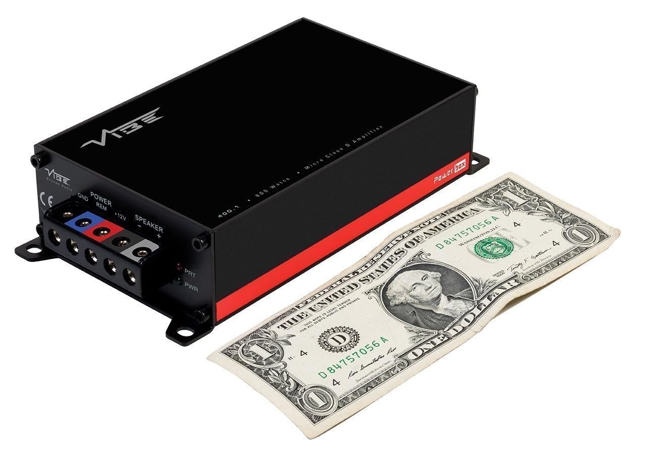
5.1 Power and Speaker Terminals

The power input section includes terminals for Ground (GND), Remote Turn-On (REM), and +12V power. The speaker output section provides terminals for connecting your subwoofer.
5.2 Input and Control Panel
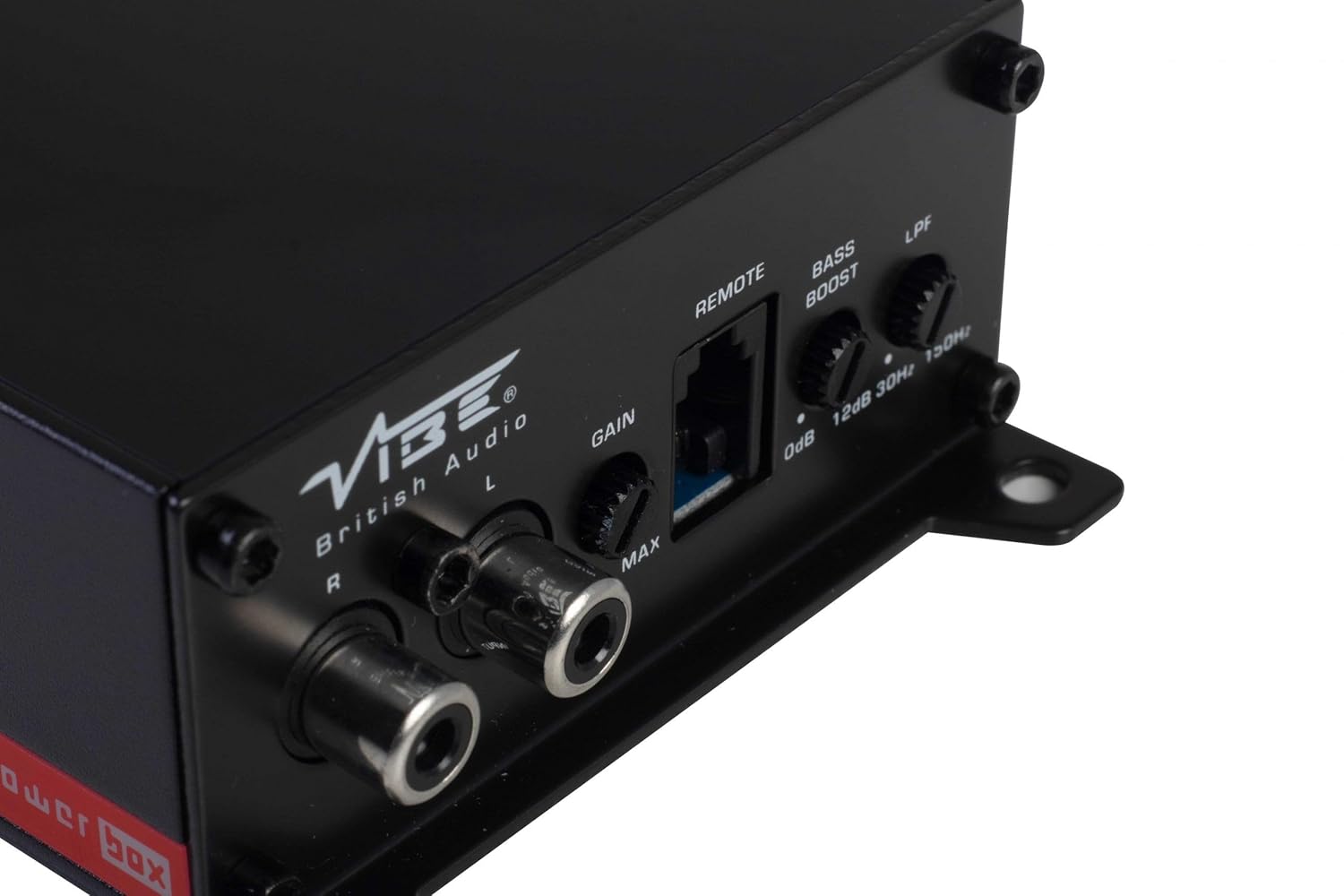
This panel features the RCA input jacks for audio signal, a Gain control knob to match the amplifier's input sensitivity to your head unit's output, a dedicated port for the remote gain control, a Bass Boost switch for enhancing low frequencies, and an LPF (Low Pass Filter) control to adjust the upper frequency limit for the subwoofer.
5.3 Remote Gain Control

The remote gain control unit connects to the amplifier via the 'REMOTE' port and allows for convenient adjustment of the subwoofer's output level from the vehicle's cabin.
6. Einrichtung und Installation
Proper installation is crucial for optimal performance and safety. If you are not confident in your ability to install the amplifier, seek professional assistance.
6.1 Montageort
Choose a mounting location that is dry, well-ventilated, and away from direct heat sources. The compact size of the Powerbox Micro allows for installation under seats, behind trim panels, or in other discreet locations. Ensure there is sufficient airflow around the ampKühler zum Kühlen.
6.2 Kabelverbindungen
Stromverkabelung:
- Verbinden Sie +12V terminal to the vehicle's positive battery terminal using a suitable gauge power cable (e.g., 8 AWG or 10 AWG). Install an in-line fuse holder within 18 inches (45 cm) of the battery.
- Verbinden Sie Masse terminal to a clean, unpainted metal surface on the vehicle's chassis. Ensure a good electrical connection. The ground cable should be of the same gauge as the power cable and as short as possible.
- Verbinden Sie REM (Remote Turn-On) terminal to the remote output of your head unit. This wire signals the amplifier to turn on and off with your stereo. If your head unit lacks a remote output, you can use an accessory wire that turns on with the ignition, or utilize the amplifier's auto-sense feature if applicable.
Lautsprecherverkabelung:
- Schließen Sie Ihren Subwoofer an den an Lautsprecherausgang terminals (+ and -). Ensure correct polarity. This amplifier is 1 Ohm stable, allowing flexibility in subwoofer impedance configurations. Refer to your subwoofer's specifications for optimal impedance matching.
Signal Input (RCA):
- Connect the RCA output from your head unit or signal processor to the INPUT (L/R) RCA jacks on the ampschwerer.
Fernsteuerung der Verstärkung:
- Plug the remote gain control unit into the dedicated FERNBEDIENUNG Port auf dem amplifier. Route the cable to a convenient location for adjustment.
ISO T Harness / ISOAWK Kit:
- For simplified installation with existing stereo looms, an optional ISOAWK kit (available separately) can be used to make the amplifier compatible with an ISO T harness. This allows for plug-and-play integration for audio signal, power, and ground, potentially eliminating the need for separate battery connections.
7. Bedienung
7.1 Erstes Einschalten
Nachdem alle Verbindungen hergestellt und überprüft wurden, schließen Sie die Fahrzeugbatterie wieder an. Schalten Sie Ihr Autoradio ein. amplifier's power indicator (PWR) should illuminate green. If the protection indicator (PRT) illuminates red, refer to the troubleshooting section.
7.2 Verstärkungseinstellung
Der Verstärkungsregler passt zu ampEingangsempfindlichkeit des Verstärkers in Bezug auf die Ausgangslautstärketage of your head unit. To set the gain:
- Drehen Sie den amplifier's Gain control to its minimum (MIN) setting.
- Set your head unit's volume to about 75-80% of its maximum.
- Spiele ein dynamisches Musikstück.
- Erhöhen Sie langsam die amplifier's Gain control until you hear distortion, then back it off slightly until the sound is clear.
The remote gain control unit allows for real-time adjustment of the subwoofer level without affecting the main system volume.
7.3 Tiefpassfilter (LPF)
The LPF control sets the upper frequency limit for the amplifier's output. This is essential for subwoofers, ensuring they only reproduce low frequencies. Adjust the LPF knob (typically 30Hz to 150Hz) to blend the subwoofer's output seamlessly with your main speakers. A common starting point is around 80-100Hz.
7.4 Bassverstärkung
The Bass Boost switch provides an adjustable low-frequency enhancement. Use this feature sparingly, as excessive bass boost can lead to distortion and potential damage to your subwoofer. Adjust the boost level (0dB to 12dB) to your preference.
8. Wartung
- Reinigung: Wischen Sie regelmäßig ab ampReinigen Sie die Außenseite des Verstärkers mit einem weichen, trockenen Tuch. Verwenden Sie keine scharfen Chemikalien oder Scheuermittel.
- Verbindungen: Regularly check all power, ground, and speaker connections to ensure they are secure and free from corrosion. Loose connections can cause performance issues or damage.
- Belüftung: Stellen Sie sicher, dass die amplifier's cooling fins are not obstructed to maintain proper heat dissipation.
9. Fehlerbehebung
| Problem | Mögliche Ursache | Lösung |
|---|---|---|
| Kein Strom (PWR-LED aus) | Sicherung durchgebrannt, lose Strom-/Masseverbindung, kein Fernsignal. | Prüfen Sie die Inline-Sicherung und vergewissern Sie sich, dass die Anschlüsse +12V, GND und REM korrekt sind. |
| Schutzmodus (PRT-LED leuchtet) | Überhitzung, Kurzschluss in der Lautsprecherverkabelung, Impedanz zu niedrig. | Ensure proper ventilation, check speaker wiring for shorts, verify speaker impedance. |
| Keine Tonausgabe | No input signal, gain too low, speaker wires disconnected. | Check RCA input connections, adjust gain, verify speaker wiring. |
| Verzerrter Klang | Gain set too high, LPF incorrectly set, poor ground connection. | Reduce gain, adjust LPF, check ground connection. |
10. Spezifikationen
- Modellnummer: POWERBOX400.1M-V7
- Amplifier Typ: Klasse D Mono Ampschwerer
- RMS-Ausgangsleistung: 1 x 400W RMS @ 1 Ohm
- Maximale Leistungsabgabe: 800 W
- Produktabmessungen (L x B x H): Ungefähr 157 x 82 x 37 mm (6.18 x 3.23 x 1.46 Zoll)
- Gewicht: Ungefähr 1.54 Pfund
- Bandtage: 12 Volt (Nennspannung)
- Maximales Versorgungsvolumentage: 12 Volt
- Montageart: Oberflächenmontage
- Hersteller: Vibe Audio
- Datum der Erstveröffentlichung: 21. Juli 2018
11. Garantie und Support
Vibe Audio products are designed and manufactured to the highest standards. For warranty information and technical support, please refer to the warranty card included with your product or visit the official Vibe Audio webBewahren Sie Ihren Kaufbeleg für Garantieansprüche auf.


