1. Einleitung
This manual provides detailed instructions for the installation, operation, and maintenance of your Linkstyle 4-in-1 Car Charger Panel, Model LS-CR08. This multifunctional panel integrates a dual USB charger, an LED voltmeter, a 12V cigarette lighter socket, and an LED rocker switch, designed for 12V/24V vehicle applications such as cars, marine boats, RVs, and trucks. Please read this manual thoroughly before installation and use to ensure proper function and safety.
2. Produktüberschreitungview
The Linkstyle 4-in-1 Car Charger Panel combines essential power and monitoring functions into a single, compact unit. Each component is designed for durability and ease of use in various vehicle environments.

Abbildung 2.1: Front view of the Linkstyle 4-in-1 Car Charger Panel, showcasing its integrated components: two USB charging ports, a digital LED voltmeter, a 12V cigarette lighter socket, and an illuminated rocker switch.
2.1 Komponenten

Abbildung 2.2: An annotated diagram highlighting each component of the 4-hole panel: the ON-OFF Switch, LED Voltmeter (display range 6-24V), 12V Power Outlet, and 2 USB Charger Sockets (Output DC 5V/4.2A).
- Dual-USB-Ladegerät: Two 5V/2.1A USB ports (total 4.2A) for simultaneous charging of two devices.
- LED Voltmeter: Digitalanzeige der Lautstärke in Echtzeittage (5-48V) of your vehicle's battery.
- 12-V-Zigarettenanzünderbuchse: Standard power outlet for various 12V accessories.
- LED Rocker Switch: An easy-to-operate ON/OFF switch with an LED indicator, rated for up to 10,000 cycles.
2.2 Packungsinhalt

Abbildung 2.3: Image showing the package contents: the assembled 4-in-1 panel, blue insulated crimp terminals, and mounting screws.
- 1 x 4-in-1 Charger Panel (pre-assembled)
- 9 x Blue Insulated Crimp Terminals
- 4 x Befestigungsschrauben
3. Einrichtung und Installation
Proper installation is crucial for the safe and effective operation of the charger panel. It is recommended to disconnect the vehicle's battery before beginning installation.
3.1 Montage
The individual components (USB charger, voltmeter, cigarette lighter, and switch) are designed for easy integration into the panel. They can be installed or replaced by screwing them into the designated holes on the panel.
Video 3.1: An instructional video demonstrating the assembly, wiring, and basic operation of the Linkstyle 4-in-1 Car Charger Panel, including testing the USB ports, cigarette lighter, and voltmeter.
3.2 Verdrahtungsanweisungen
Beachten Sie den untenstehenden Schaltplan für die korrekten elektrischen Anschlüsse. Stellen Sie sicher, dass alle Verbindungen fest sitzen und ordnungsgemäß isoliert sind.

Abbildung 3.1: Detailed wiring diagram illustrating the connections for the power outlet, voltmeter, USB charger, and switch. It specifies that the brass prong is negative ('-') and the silver prong is positive ('+') for the outlet, charger, and voltmeter, while the switch has specific silver and gold prongs for positive and negative connections.
- Terminals identifizieren: For the Power Outlet, Voltmeter, and USB Charger, the silver prong is the positive (+) terminal, and the brass prong is the negative (-) terminal.
- Schalterverdrahtung: The rocker switch typically has three prongs. Connect the positive (+) input to one of the silver prongs, the positive (+) output to the other silver prong, and the gold prong to the negative (-) circuit.
- Komponenten verbinden: Wire the positive terminals of the USB Charger, Voltmeter, and Power Outlet to the positive output of the rocker switch.
- Erdung: Connect all negative terminals of the USB Charger, Voltmeter, and Power Outlet, along with the gold prong of the switch, to a common ground point or the vehicle's negative battery terminal.
- Energiequelle: Connect the positive input of the rocker switch to a fused 12V/24V power source from your vehicle's battery or accessory circuit.
Notiz: Always use appropriate gauge wiring and an inline fuse (not included) for protection against overcurrent. Consult a professional if you are unsure about electrical wiring.
4. Bedienung
4.1 Ein-/Ausschalten
Use the integrated LED rocker switch to turn the entire panel's power supply ON or OFF. The LED indicator on the switch will illuminate when power is active.
4.2 Using the Dual USB Charger
Plug your USB-compatible devices into either of the two USB ports. The charger automatically detects your device and delivers optimal charging speed up to 2.1A per port, with a total output of 4.2A.
4.3 Monitoring Voltage with the LED Voltmeter
The digital LED voltmeter continuously displays the real-time voltage of your vehicle's battery (5-48V). This allows you to monitor battery health and prevent unexpected power issues.
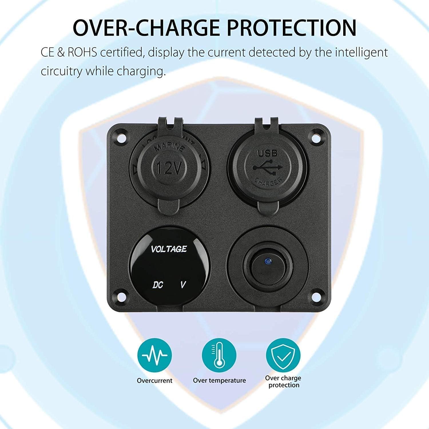
Abbildung 4.1: Diagram illustrating the built-in protection features of the panel, including safeguards against overcurrent, over-temperature, and over-charge, certified by CE & ROHS.
Normale Voltage Bereiche:
- Vor dem Starten des Fahrzeugs: 13.4 V - 14.8 V
- After starting the vehicle: 12.2 V - 12.8 V
Wenn die Lautstärketage drops below 12V, it indicates an abnormal voltage, and the battery should be checked or replaced as soon as possible.
4.4 Using the 12V Cigarette Lighter Socket
Insert any compatible 12V accessory into the cigarette lighter socket. Ensure the accessory's power requirements do not exceed the panel's maximum current rating.
5. Sicherheitshinweise
- Vor der Durchführung jeglicher elektrischer Arbeiten muss immer die Fahrzeugbatterie abgeklemmt werden.
- Ensure proper wiring polarity (positive to positive, negative to negative) to prevent damage to the device and vehicle.
- Use an appropriate inline fuse for the main power input to protect against overcurrent.
- Do not exceed the maximum current rating of the panel or individual components.
- Keep the rubber caps on the USB ports and cigarette lighter socket when not in use to protect against water and dust.
- This product is designed for 12V/24V DC systems only. Do not connect to AC power.
Abbildung 5.1: The Linkstyle 4-in-1 Car Charger Panel features protective rubber caps for the USB ports and cigarette lighter socket, enhancing its waterproof and dustproof capabilities.
6. Spezifikationen
| Besonderheit | Spezifikation |
|---|---|
| Modellnummer | LS-CR08 |
| Eingangslautstärketage | 12V / 24V DC |
| USB-Ausgang | 5V / 4.2A (2.1A per port) |
| Voltmeter-Bereich | 5 V - 48 V |
| Zigarettenanzünder-Ausgabe | 12 V |
| Technische Daten | 4.13 x 3.42 x 1.38 Zoll (10.5 x 8.7 x 3.5 cm) |
| Artikelgewicht | 4.2 Unzen (119 Gramm) |
| Material | Robuster ABS-Kunststoff |
| Kompatibilität | Cars, Motorcycles, ATVs, RVs, Boats, Trucks |

Abbildung 6.1: Image displaying the physical dimensions of the panel, measuring approximately 10.5 cm (4.13 inches) in width and 8.7 cm (3.42 inches) in height.

Abbildung 6.2: Illustrates the wide compatibility of the charger panel, suitable for installation in various vehicles including cars, motorcycles, trucks, ATVs, boats, and RVs.
7. Fehlerbehebung
- Kein Strom am Bedienfeld:
- Prüfen Sie alle Kabelverbindungen auf Lockerheit oder Korrosion.
- Prüfen Sie, ob die Fahrzeugbatterie ausreichend geladen ist.
- Inspect the inline fuse (if installed) for being blown and replace if necessary.
- Ensure the rocker switch is in the 'ON' position.
- USB-Anschlüsse laden nicht:
- Confirm the panel has power (voltmeter or switch LED should be active).
- Um Kabel-/Geräteprobleme auszuschließen, versuchen Sie es mit einem anderen USB-Kabel oder -Gerät.
- Ensure the device's power requirements do not exceed the USB port's output (2.1A per port).
- Voltmeter Displaying Incorrect Readings:
- Check the voltmeter's wiring connections for secure contact.
- Compare the reading with another known accurate voltmeter to verify.
- Cigarette Lighter Socket Not Working:
- Ensure the panel is powered on.
- Test with a different 12V accessory to confirm the issue is not with the accessory.
- Check for any debris or foreign objects inside the socket.
8. Wartung
- Regularly inspect all wiring and connections for signs of wear, corrosion, or damage.
- Keep the panel clean and free from dust and debris. Use a soft, dry cloth for cleaning.
- Ensure the rubber caps are properly seated over the USB ports and cigarette lighter socket when not in use to maintain their waterproof and dustproof properties.
- Avoid exposing the panel to extreme temperatures or harsh chemicals.
9. Garantie und Support
For warranty information or technical support, please refer to the product packaging or contact Linkstyle customer service through their official website or the retailer where the product was purchased. Please have your model number (LS-CR08) and purchase details available when contacting support.


