1. Einleitung
The E70-433T14S is a wireless transceiver module designed for reliable data communication. It operates within the 425~450.5MHz frequency band, with a default setting of 433MHz. This module integrates the CC1310 chip from Texas Instruments, providing robust performance. It features TTL level output and a 3.3V IO port voltage, utilizing a 24MHz industrial high-precision low-temperature drift crystal for stability. The module includes a Forward Error Correction (FEC) algorithm to enhance data reliability and transmission range by proactively correcting interfered data packets.
The E70-433T14S comes with a built-in low-power multifunctional wireless serial program, allowing users to perform secondary development as needed. This manual provides essential information for setup, operation, and maintenance.
2. Hauptmerkmale
- Kommunikationsentfernung: Tested up to 1.5 km under optimal conditions.
- Sendeleistung: Maximum 25mW, with software-adjustable multi-level power settings.
- Frequenzband: Supports the global license-free ISM 433MHz band.
- Air Data Rate: Configurable from 2.5kbps to 168kbps.
- Geringer Stromverbrauch: Designed for battery-supplied applications, with receiving current significantly lower than similar products, supporting ultra-low power consumption in air wake mode.
- Datenübertragung: Capable of achieving up to 115200bps continuous frame unlimited-packet length transmission.
- Stromversorgung: Supports 2.2V to 3.8V. A power supply over 3.3V is recommended for optimal performance.
- Industriequalitätsdesign: Funktioniert zuverlässig bei Temperaturen von -40 °C bis 85 °C.
- Antennenschnittstelle: Features an IPEX access point; stamp hole option is available for secondary development and integration.
- Fehlerkorrektur: Incorporates FEC (Forward Error Correction) algorithm for improved data reliability.
3. Anwendungen
The E70-433T14S module is suitable for a wide range of applications requiring wireless data transmission, including:
- Home security alarm systems and remote keyless entry.
- Smart home and industrial sensor networks.
- Wireless alarm security systems.
- Building automation solutions.
- Wireless industrial-grade remote control systems.
- Health care products requiring wireless connectivity.
- Erweiterte Zählerablesearchitektur (AMI).
- Smart agriculture and smart oil field monitoring.
- Environmental monitoring, including temperature and humidity sensors.
4. Modul vorbeiview
The E70-433T14S module is a compact surface-mount device (SMD) designed for easy integration into various electronic systems. Below are images illustrating the module's physical characteristics and pinout.
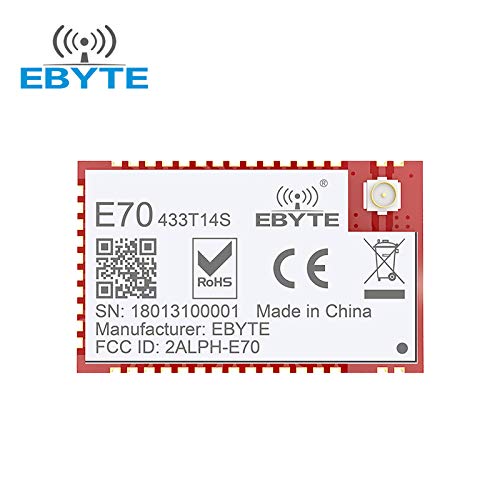
Abbildung 1: Front view of the EBYTE E70-433T14S wireless module, showing the model number, EBYTE logo, RoHS and CE certifications, serial number, manufacturer, and FCC ID.
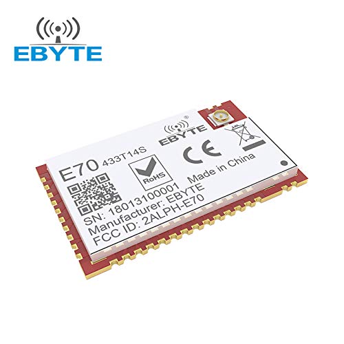
Abbildung 2: Abgewinkelt view of the EBYTE E70-433T14S wireless module, highlighting its compact form factor and pin headers.
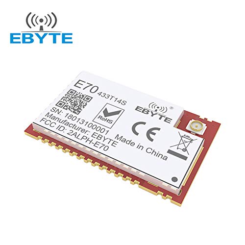
Abbildung 3: Another angled perspective of the EBYTE E70-433T14S module, providing a clear view of the antenna connector.
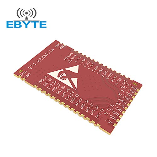
Abbildung 4: Unten view of the EBYTE E70-433T14S module, illustrating the pinout diagram for various General Purpose Input/Output (GPIO) pins, power, and ground connections.
5. Technische Daten
| Parameter | Wert |
|---|---|
| IC: | CC1310 |
| Frequenz: | 431~446.5MHz (Default: 433MHz) |
| Sendeleistung: | 14dBm (25mW), software adjustable |
| Kommunikationsentfernung: | Up to 1.0 km (typical), 1.5 km (maximum tested) |
| Schnittstelle: | UART/IO |
| IO Port Voltage: | 3.3V (TTL level) |
| Netzteil Voltage: | 2.2V~3.8V (3.3V+ recommended for optimal performance) |
| Crystal Vibration: | 24MHz industrial high-precision low-temperature drift |
| Betriebstemperatur: | -40°C bis 85°C |
| Air Data Rate: | 2.5 kbps ~ 168 kbps |
| Fehlerkorrektur: | FEC (Forward Error Correction) algorithm |
| Antenne: | IPEX-Zugangspunkt, stamp hole optional |
6. Einrichtung und Installation
6.1 Stromversorgungsanschluss
Connect the module to a stable power supply within the 2.2V to 3.8V range. For optimal performance and stability, a power supply of 3.3V or higher is recommended. Ensure correct polarity (VCC and GND pins) to prevent damage to the module.
6.2 Antennenanschluss
Attach a suitable 433MHz antenna to the IPEX connector on the module. For best range and signal integrity, ensure the antenna is correctly matched and positioned away from metallic obstructions. If using the stamp hole option, ensure proper soldering for antenna connection.
6.3 UART/IO Interface Connection
Connect the module's UART (Universal Asynchronous Receiver/Transmitter) pins (TXD, RXD) to your host microcontroller or system. The IO port voltage is 3.3V. Ensure proper level shifting if your host system operates at a different voltage (e.g., 5V) to avoid damaging the module.
6.4 Softwarekonfiguration
The module comes with a pre-programmed low-power multifunctional wireless serial program. Users can configure parameters such as frequency, transmission power, and air data rate via serial commands. For advanced functionalities or custom applications, secondary development using the CC1310's capabilities is supported.
7. Bedienungsanleitung
7.1 Datenübertragung und -empfang
Once properly configured, the module can transmit and receive data wirelessly. Data sent to the module's UART TXD pin will be transmitted over the air, and data received wirelessly will be output via the UART RXD pin. Ensure that both transmitting and receiving modules are configured with compatible parameters (frequency, air data rate, etc.).
7.2 Vorwärtsfehlerkorrektur (FEC)
The integrated FEC algorithm automatically adds redundant data to transmissions, allowing the receiver to detect and correct certain errors that may occur due to interference or signal degradation. This feature improves the reliability and effective range of communication, especially in noisy environments. No direct user intervention is typically required for FEC operation.
7.3 Low Power Operation
The E70-433T14S is designed for low power consumption, making it suitable for battery-powered devices. Utilize the module's low-power modes and air wake functionality to minimize energy usage in applications where continuous operation is not required. Refer to the detailed CC1310 datasheet and EBYTE's programming guide for specific low-power mode configurations.
8. Wartung
- Handhabung: Handle the module with care to avoid physical damage. Electrostatic discharge (ESD) precautions should be observed during handling and installation.
- Umfeld: Operate the module within its specified temperature range (-40°C to 85°C) and avoid exposure to excessive moisture or corrosive environments.
- Reinigung: If necessary, clean the module gently with a dry, soft cloth. Do not use liquid cleaners or solvents.
- Antenne: Ensure the antenna connection remains secure and the antenna itself is undamaged for optimal performance.
9. Fehlerbehebung
- Kein Strom: Überprüfen Sie, ob die Stromversorgungsspannungtage is within the 2.2V-3.8V range and correctly connected to the VCC and GND pins. Check for any short circuits.
- Keine Kommunikation:
- Ensure UART connections (TXD, RXD) are correct and not swapped.
- Verify that the host microcontroller's UART settings (baud rate, parity, stop bits) match the module's configuration.
- Check if both transmitting and receiving modules are operating on the same frequency and air data rate.
- Poor Range/Signal:
- Stellen Sie sicher, dass die Antenne ordnungsgemäß angeschlossen und unbeschädigt ist.
- Check for obstructions (especially metallic) between the transmitting and receiving modules.
- Verify that the transmission power is set to an appropriate level (maximum 25mW).
- Environmental interference can affect range; consider testing in different locations.
- Modulüberhitzung: Ensure adequate ventilation, especially if operating at maximum transmission power for extended periods. Verify power supply voltage is not exceeding the maximum limit.
10. Compliance-Informationen
The E70-433T14S module is designed to comply with relevant industry standards. As indicated on the module, it is RoHS compliant and carries the CE mark, signifying conformity with European health, safety, and environmental protection standards. The module also has an FCC ID: 2ALPH-E70, indicating compliance with Federal Communications Commission regulations for radio frequency devices.
11. Unterstützung
For further technical support, detailed datasheets, programming guides, or inquiries, please visit the official EBYTE webWebsite: www.cdebyte.com


