1. Einleitung
The EPEVER Tracer1210AN MPPT Solar Charge Controller is designed to efficiently manage power from your solar panels to charge batteries. It features advanced Maximum Power Point Tracking (MPPT) technology, ensuring high tracking efficiency of over 99.5%. This controller supports 12V and 24V battery systems automatically and can handle a maximum PV input voltage of 100V. It is compatible with various battery types, including sealed lead-acid, gel, flooded, and lithium batteries. The built-in LCD screen displays key charging parameters, and multiple connectivity options allow for personalized settings and monitoring via remote meter, mobile app, or PC software.
2. Produktmerkmale
The Tracer1210AN controller integrates several features for optimal performance and user interaction.

- LCD Anzeige: Shows real-time operating data and fault information.
- Schaltfläche „Auswahl“: Used to navigate through different display interfaces.
- Eingabetaste: Used to confirm selections or enter settings menus.
- Befestigungsbohrungen: Für eine sichere Installation des Controllers.
- Anschluss für Temperatursensor: Connects the Remote Temperature Sensor (RTS) for accurate battery temperature compensation.
- Solarpanel-Anschlüsse: Verbindet sich mit der Solarzellenanlage.
- Batterieklemmen: Wird mit der Batteriebank verbunden.
- Lastanschlüsse: Anschlussmöglichkeiten für Gleichstromverbraucher.
- COM Port (RS485): For communication with accessories like the MT50 remote meter, PC software, or mobile app.

3. Einrichtung und Installation
Eine korrekte Installation ist entscheidend für den sicheren und effizienten Betrieb Ihres Solarladereglers. Befolgen Sie diese Schritte sorgfältig.
3.1 Auspacken und Komponenten
Before installation, ensure all components are present and undamaged. The package typically includes the Tracer1210AN controller, an MT50 remote meter, a Remote Temperature Sensor (RTS), and an RS485 PC communication cable.

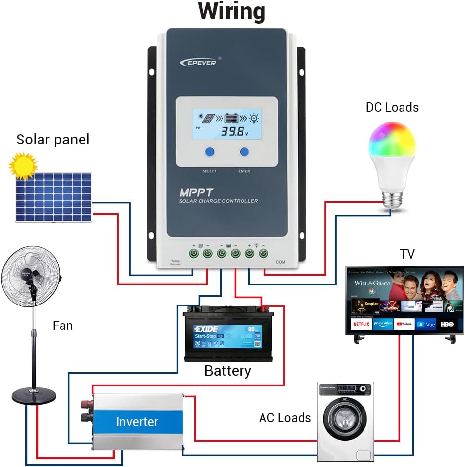
3.2 Schaltplan
Connect the components in the specified order to prevent damage. The connection order is: Battery → Solar Panel → Load. The disassembly order is the reverse: Load → Solar Panel → Battery.
3.3 Communication Ports and Accessories
The controller features various ports for enhanced monitoring and control.

- Remote Temperature Sensor (RTS): Connect the RTS300R47K3.81A to the designated port for accurate battery temperature compensation. The standard cable length is 3m.
- RS485-Kommunikationsanschluss: This RJ45 port allows connection to various accessories for monitoring and parameter setting.
3.4 Installationsschritte
- Mount the controller securely using the provided mounting holes.
- Connect the battery to the controller's battery terminals. Ensure correct polarity.
- Connect the solar panel to the controller's solar panel terminals. Ensure correct polarity.
- Connect the DC loads to the controller's load terminals. Ensure correct polarity.
- Connect the temperature sensor probe to the controller.
3.5 Video: Unboxing and Installation
Watch this video for a visual guide on unboxing and installing the EPEVER Tracer-AN controller and its accessories.
4. Bedienungsanleitung
This section covers basic operation and how to configure essential settings on your controller.
4.1 Manual Control Mode
The controller supports manual control of the load. Press the 'ENTER' button to toggle the load on or off.
4.2 Setting the Battery Type
It is essential to set the correct battery type for optimal charging and battery longevity. The controller supports various battery types including Sealed (default), Gel, Flooded, and different Lithium battery configurations.
So stellen Sie den Batterietyp ein:
- Press and hold the 'ENTER' button for 5 seconds when the battery voltage interface is displayed.
- Press the 'SELECT' button when the battery type interface is flashing to cycle through available battery types.
- Press the 'ENTER' button to confirm your selection.
4.3 Setting the Load Mode
The load working mode determines how the connected DC loads operate. Options include Light ON/OFF, various timer settings, test mode, and manual mode.
To set the load mode:
- Press and hold the 'ENTER' button for 5 seconds when the load mode interface is displayed.
- Press the 'SELECT' button when the load mode interface is flashing to cycle through available modes.
- Press the 'ENTER' button to confirm your selection.
5. Spezifikationen
Below are the technical specifications for the Tracer1210AN MPPT Solar Charge Controller.
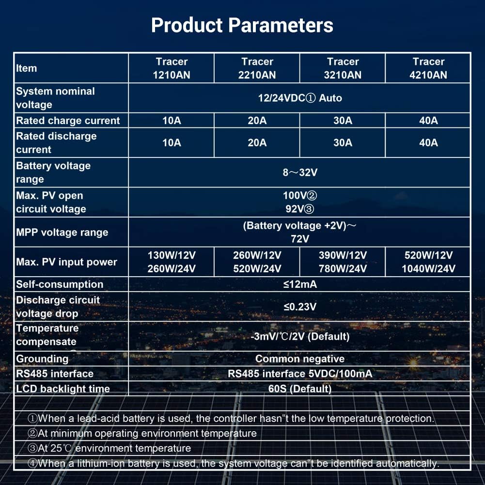
| Parameter | Value (Tracer1210AN) |
|---|---|
| System-Nennvolumentage | 12 / 24VDC Auto |
| Nennladestrom | 10 A |
| Nennentladestrom | 10 A |
| Batterie Voltage Reichweite | 8 bis 32 V |
| max. PV Leerlauf Voltage | 100V (bei 25°C Umgebungstemperatur) |
| MPP-Voltage Reichweite | Batterie Voltage +2V ~ 72V |
| Max. PV-Eingangsleistung | 130 W/12 V, 260 W/24 V |
| Eigenverbrauch | ≤12 mA |
| Entladestromkreis Voltage Tropfen | ≤ 0.23 V |
| Temperature Compensate | -3mV/°C/2V (Standard) |
| Erdung | Gemeinsames Negativ |
| RS485-Schnittstelle | 5 VDC / 100 mA |
| LCD-Hintergrundbeleuchtungszeit | 60S (Standard) |
6. Zubehör
The EPEVER Tracer1210AN controller is often bundled with or compatible with several accessories to enhance its functionality.
- MT50 Remote Meter: This remote meter can display various operating data and fault information. It features easy-to-operate buttons and a clear numeric display. It is used for monitoring and setting controller parameters.
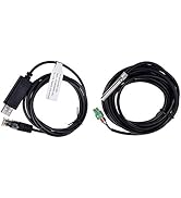
- Remote Temperature Sensor (RTS300R47K3.81A): Acquires battery temperature for accurate temperature compensation of control parameters. The standard length of the cable is 3m.
- USB to RS485 Cable (CC-USB-RS485-150U): Used to connect the controller to a PC for monitoring and setting parameters via Solar Station PC software. The cable length is 1.5m.
- OTG Cable (OTG-12CM): Used to connect a mobile communication cable to achieve real-time monitoring and parameter modification via a mobile APP.
- WiFi Serial Adapter (eBox-WiFi-01): Allows monitoring and setting parameters via mobile APP software through WiFi signals.
- RS485 to Bluetooth Adapter (eBox-BLE-01): Enables monitoring and setting parameters via mobile APP software through Bluetooth signals.
- Logger (eLOG01): Records the operating status of the controller for later review.

7. Fehlerbehebung
If you encounter issues with your EPEVER Tracer1210AN controller, refer to the following common troubleshooting tips:
- Keine Anzeige auf dem LCD: Überprüfen Sie die Batterieanschlüsse und stellen Sie sicher, dass die Batteriespannung ausreichend ist.tage liegt im Betriebsbereich.
- Kein Aufladen: Verify solar panel connections and ensure sufficient sunlight. Check for any shading on the solar panels. Confirm the battery type setting is correct.
- Laden funktioniert nicht: Check load connections and ensure the load mode is set correctly (e.g., Manual ON, Light ON/OFF). Verify that the battery voltage liegt über dem niedrigen Voltage Trennschwelle.
- Ungenaue Temperaturmessung: Ensure the Remote Temperature Sensor (RTS) is properly connected and positioned near the battery.
- Kommunikationsprobleme: Check the RS485 cable connections to the remote meter, PC, or adapter. Ensure drivers are installed for PC communication.
For more detailed troubleshooting, consult the full product manual or contact EPEVER customer support.
8. Wartung
Regular maintenance helps ensure the longevity and optimal performance of your solar charge controller.
- Sauberkeit: Halten Sie den Controller sauber und frei von Staub und Schmutz. Verwenden Sie zum Reinigen ein trockenes Tuch.
- Verbindungen: Überprüfen Sie regelmäßig alle Kabelverbindungen auf festen Sitz und Korrosion. Lose Verbindungen können zu Überhitzung und Schäden führen.
- Belüftung: Ensure adequate airflow around the controller to facilitate heat dissipation. Do not block the heat sink fins.
- Batteriezustand: Batterievol überwachentage and health regularly. Ensure the battery type setting on the controller matches your battery.
- Firmware-Updates: Überprüfen Sie die Angaben des Herstellers webWebsite für alle verfügbaren Firmware-Updates zur Leistungsverbesserung oder zum Hinzufügen neuer Funktionen.
9. Garantie und Support
EPEVER products are designed for reliability and performance. For warranty information and technical support, please refer to the official EPEVER webBesuchen Sie unsere Website oder wenden Sie sich an Ihren lokalen Händler.
You can also visit the official iSunergy store on Amazon for product information and support: iSunergy Amazon Store.