1. Sicherheitshinweise
Read all instructions carefully before beginning installation. Failure to follow these instructions may result in electrical shock, fire, or personal injury.
- Vor Installation oder Wartung muss immer die Stromzufuhr am Sicherungsautomaten oder Sicherungskasten unterbrochen werden.
- Alle Verkabelungen müssen den nationalen und lokalen Elektrovorschriften entsprechen. Wenn Sie mit Verkabelungen nicht vertraut sind, wenden Sie sich bitte an einen qualifizierten Elektriker.
- Ensure the installation site can support the weight of the fan (approximately 3.53 kg).
- Betreiben Sie den Ventilator nicht, wenn die Flügel oder das Gehäuse beschädigt sind.
- Halten Sie einen Mindestabstand von 2.1 Metern (7 Fuß) zwischen dem Boden und der Unterkante der Lüfterflügel ein.
- Fügen Sie keine Objekte in den Bewegungsbereich der Lüfterflügel ein.
2. Packungsinhalt
Verify that all components listed below are present before beginning installation. If any parts are missing or damaged, do not proceed with installation and contact customer support.
- Montage des Motorgehäuses
- Fan Blades (4) - Reversible white/bleached oak
- Klingenhalterungen (4)
- Downrod
- Überdachung
- Montagehalterung
- Montage des Beleuchtungssatzes
- Mushroom Globe Glass
- Zugketten (2)
- Hardware-Set (Schrauben, Unterlegscheiben, Drahtverbinder)
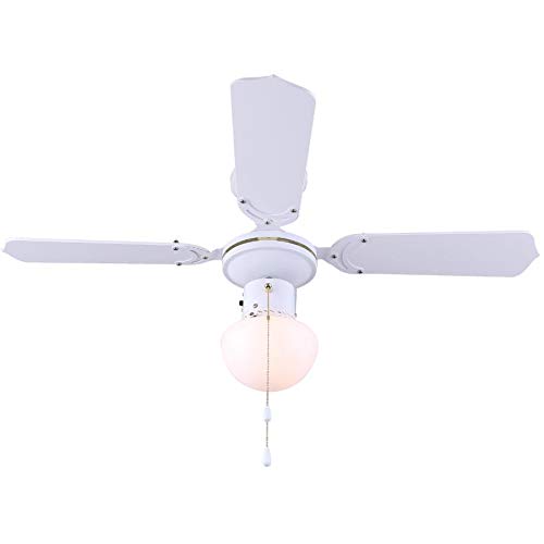
Abbildung 2.1: Überview of the Canarm Unity Ceiling Fan with Light, displaying the motor housing, four blades, and the central mushroom globe light.
3. Einrichtung und Installation
Eine Installation durch einen Fachmann wird empfohlen. Stellen Sie sicher, dass die Stromzufuhr am Sicherungskasten unterbrochen ist, bevor Sie fortfahren.
3.1 Montage des Lüfters
- Befestigen Sie die Montagehalterung an der Deckenanschlussdose. Stellen Sie sicher, dass die Anschlussdose fest mit der Gebäudekonstruktion verbunden ist und das Gewicht des Ventilators tragen kann.
- Feed the electrical wires from the junction box through the center hole of the mounting bracket.
- Befestigen Sie die Verlängerungsstange am Motorgehäuse und achten Sie darauf, dass alle Schrauben fest angezogen sind.
- Carefully lift the fan assembly and hang it from the mounting bracket using the hook provided on the downrod.
3.2 Elektrische Anschlüsse
Schließen Sie die elektrischen Leitungen des Ventilators gemäß folgender Anleitung an die Hausverkabelung an:
- Connect the green/bare copper wire (ground) from the fan to the ground wire from the junction box.
- Connect the white wire (neutral) from the fan to the white wire from the junction box.
- Connect the black wire (hot for fan) from the fan to the black wire from the junction box.
- Connect the blue wire (hot for light) from the fan to the black or blue wire from the junction box (if separate light switch).
- Sichern Sie alle Verbindungen mit Lüsterklemmen und achten Sie darauf, dass keine losen Drahtlitzen freiliegen.
3.3 Anbringen der Lüfterflügel
- Attach each blade to a blade bracket using the provided screws. Ensure the desired blade finish (white or bleached oak) is facing downwards.
- Secure each blade assembly to the motor housing using the screws provided. Ensure all screws are tight.
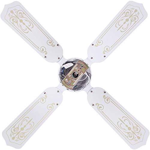

Figure 3.3: Images showing the blade attachment points on the motor housing (left) and the assembled blades from a top-down perspective (right).
3.4 Installation des Beleuchtungssets
- Connect the light kit wires to the corresponding wires from the fan motor housing (usually white to white, blue to black).
- Secure the light kit assembly to the bottom of the motor housing with the provided screws.
- Install the appropriate light bulb(s) (not included) into the sockets.
- Carefully attach the mushroom globe glass to the light kit by twisting or securing with screws, depending on the design.

Abbildung 3.4: Nahaufnahme view of the fan's light kit with the mushroom globe glass.
3.5 Letzte Schritte
- Carefully slide the canopy up against the ceiling and secure it with the provided screws.
- Stellen Sie die Stromversorgung am Leistungsschalter wieder her.
4. Bedienungsanleitung
The Canarm Unity ceiling fan is operated by two pull chains.
- Lüfterdrehzahlregelung: One pull chain controls the fan speed. Pull the chain repeatedly to cycle through the three available speeds (High, Medium, Low) and Off.
- Lichtsteuerung: The second pull chain controls the light. Pull the chain to turn the light On or Off.
- Klingenumkehr: To change the direction of the fan blades (e.g., for summer cooling or winter heat circulation), locate the slide switch on the motor housing. With the fan off, slide the switch to the opposite position. This fan features reversible white/bleached oak blades.

Figure 4.1: The Canarm Unity fan installed, demonstrating its function within a living space.
5. Wartung
Regelmäßige Wartung gewährleistet optimale Leistung und verlängert die Lebensdauer Ihres Deckenventilators.
- Reinigung: Reinigen Sie die Lüfterflügel und das Motorgehäuse regelmäßig mit einem weichen, feuchten Tuch.amp Tuch. Keine Scheuer- oder Lösungsmittel verwenden.
- Befestigungsschrauben: Check all screws on the blade attachments and mounting hardware annually. Tighten any loose screws to prevent wobbling or noise.
- Glühbirnenwechsel: Disconnect power before replacing light bulbs. Allow bulbs to cool before handling. Use bulbs of the correct wattage und Typ gemäß den Angaben in den elektrischen Kenndaten des Lüfters.
6. Fehlerbehebung
Vor Beginn jeglicher Reparaturarbeiten muss sichergestellt werden, dass die Stromzufuhr am Sicherungsautomaten unterbrochen ist.
| Problem | Mögliche Ursache | Lösung |
|---|---|---|
| Lüfter startet nicht | No power to the fan; Loose wire connections; Motor malfunction | Check circuit breaker/fuse; Verify all wire connections are secure; Contact a qualified electrician or customer support. |
| Licht funktioniert nicht | Bulb faulty or loose; Loose wire connections; Light kit malfunction | Replace bulb; Tighten bulb; Check light kit wiring; Contact customer support. |
| Lüfter wackelt | Lose Klingenschrauben; Unwucht der Klingen; Lose Montagehalterung | Tighten all blade screws; Ensure blades are balanced (balancing kit may be needed); Verify mounting bracket is secure. |
| Lauter Betrieb | Loose screws; Motor bearings; Canopy rubbing ceiling | Check and tighten all screws; Ensure canopy is not touching the ceiling; If motor noise persists, contact customer support. |
7. Spezifikationen
| Marke | Canarm |
| Modellnummer | CF2336411L |
| Technische Daten | 91.44 x 91.44 x 20.32 cm (36 x 36 x 8 Zoll) |
| Artikelgewicht | 3.53 kg |
| Farbe | Weiß |
| Anzahl der Klingen | 4 |
| Klingenende | Reversible White/Bleached Oak |
| Anzahl der Geschwindigkeiten | 3 |
| Leistung/Watttage | 60 Watt |
| Montagetyp | Downrod-Halterung |
| Controllertyp | Zugkettensteuerung |
8. Garantie und Support
This product is covered by the manufacturer's standard warranty. Please refer to the warranty card included in your original packaging for specific terms and conditions.
For technical assistance, missing parts, or warranty claims, please contact Canarm customer support. Contact information can typically be found on the manufacturer's webauf der Website oder auf der Produktverpackung.
Bitte bewahren Sie dieses Handbuch zum späteren Nachschlagen auf.


