Einführung
This manual provides detailed instructions for the installation, operation, and maintenance of your Nilight 90110E 5 Gang Rocker Switch Panel. Designed for automotive, marine, and RV applications, this pre-wired panel offers convenient control for various accessories. Please read this manual thoroughly before installation and use to ensure proper function and safety.
Produkt überview
Merkmale
- Pre-wired aluminum panel with 5 rocker switches.
- 5-pin SPST (Single Pole Single Throw) ON/OFF switch design.
- Blue LED backlighting for clear visibility.
- Includes night glow DIY stickers for switch customization.
- Compatible with 12V and 24V DC systems.
- Reinforced aluminum panel and well-conductive pins for durability.
Packungsinhalt
Überprüfen Sie, ob alle Komponenten in Ihrem Paket vorhanden sind:
- 1 x Pre-wired 5 Gang Rocker Switch Panel
- 1 x Set of Stainless Steel Screws
- 2 x Sets of Universal DIY Stickers

Abbildung 1: Packungsinhalt
Setup und Installation
The Nilight 90110E switch panel is designed for easy installation due to its pre-wired configuration. Follow these steps for a secure and functional setup.
Abmessungen und Montage
Before installation, ensure you have adequate space for the panel. The panel dimensions are approximately 15 cm (Length) x 7 cm (Width) x 6 cm (Height).

Abbildung 2: Produktabmessungen
- Ort auswählen: Choose a flat, secure surface in your vehicle or boat dashboard for mounting. Ensure there is sufficient clearance behind the panel for wiring.
- Schnittöffnung: Carefully cut an opening in the chosen surface according to the panel's dimensions. It is recommended to use a template for accuracy.
- Sicheres Panel: Insert the switch panel into the opening. Use the provided stainless steel screws to secure the panel firmly in place.
Kabelanschluss
The panel comes pre-wired for simplified connection. Each switch is a 5-pin SPST type. Refer to the wiring diagram below for correct connections.
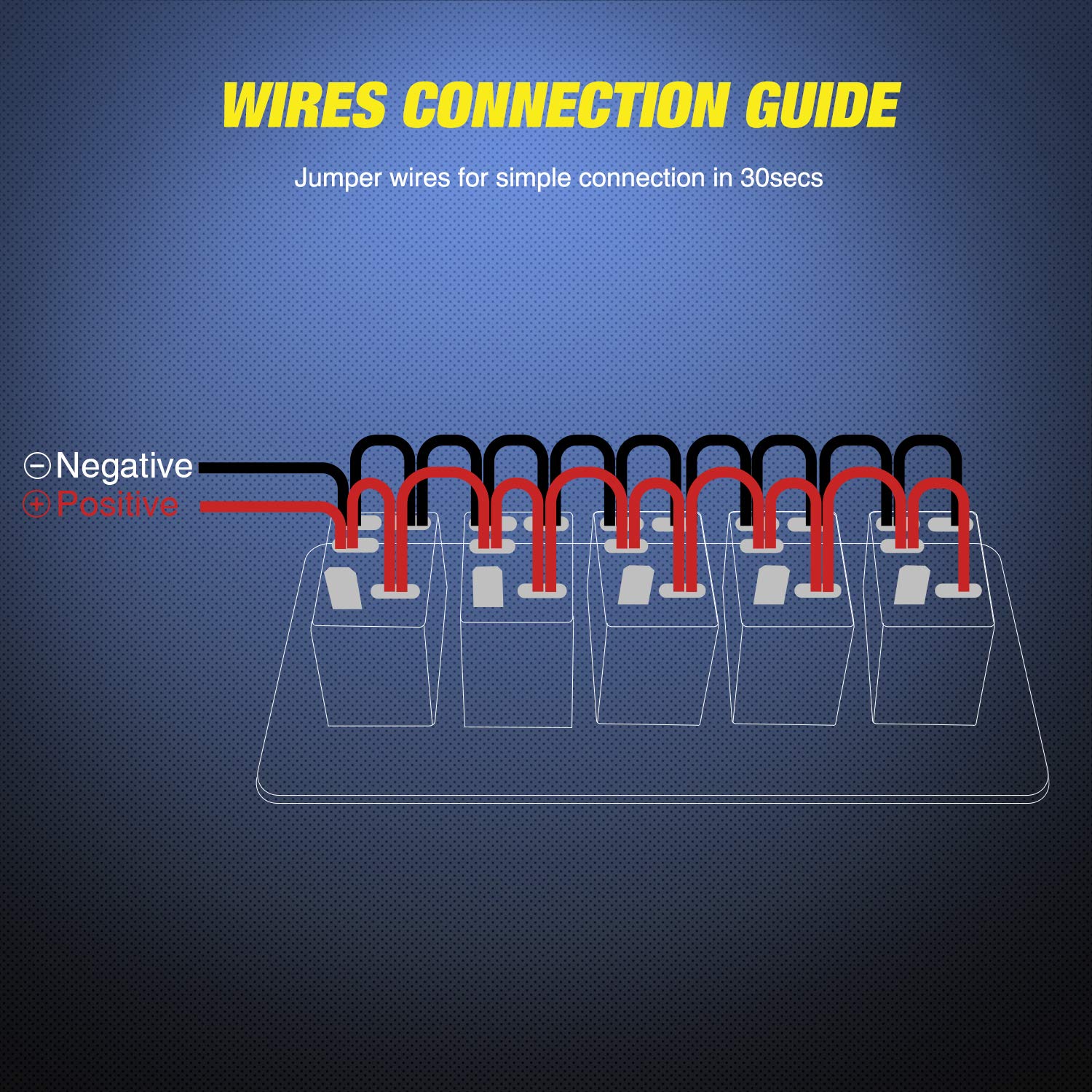
Figure 3: Wires Connection Guide
- Leistungsaufnahme: Connect the main positive (+) wire from your 12V or 24V DC power source to the designated positive input terminal on the panel.
- Masseanschluss: Connect the main negative (-) wire from your power source to the designated negative ground terminal.
- Zubehöranschlüsse: For each switch, connect the positive wire of the accessory (e.g., LED light bar, horn) to the corresponding output terminal of the switch. The negative wire of the accessory should be connected to a common ground point.
- Pre-wired Harness: The internal jumper wires are already connected for common positive and negative distribution to each switch. Ensure these connections remain secure.

Figure 4: Easy Installation with Pre-wired Harness
Bedienungsanleitung
Each rocker switch on the panel controls a single circuit. The switches are SPST (Single Pole Single Throw) ON/OFF type.
- Ein-/Ausschalten: To activate an accessory, press the top part of the corresponding rocker switch. The blue LED backlight will illuminate, indicating the switch is in the 'ON' position.
- Ausschalten: To deactivate an accessory, press the bottom part of the rocker switch. The blue LED backlight will turn off, indicating the switch is in the 'OFF' position.
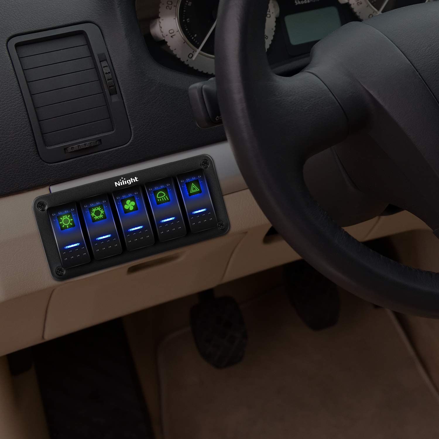
Figure 5: Panel in Operation
Wartung
Reinigung
To clean the switch panel, use a soft, damp cloth. Avoid abrasive cleaners or solvents that could damage the aluminum finish or switch components.
Switch Disconnection
The terminals connected to the switches are designed for easy disconnection. To separate a terminal from a switch, gently press down on the clip mechanism and pull the terminal away.

Figure 6: Easy Terminal Disconnection
Customization with DIY Stickers
The included DIY stickers allow you to label each switch according to its function. These stickers glow in the dark for improved visibility at night.

Figure 7: DIY Sticker Sheet
- Aufkleber auswählen: Choose the appropriate sticker for each switch function.
- Aufkleber anbringen: Carefully peel the sticker and apply it to the designated area on the rocker switch.
Fehlerbehebung
If you encounter issues with your Nilight 90110E switch panel, refer to the following common problems and solutions:
- Kein Strom am Bedienfeld:
- Check main power input connection to ensure it is secure and receiving 12V-24V DC.
- Verify the ground connection is properly established.
- Inspect any inline fuses in your power circuit and replace if blown.
- Switch Not Activating Accessory:
- Ensure the accessory's positive wire is correctly connected to the switch output terminal.
- Confirm the accessory's negative wire is properly grounded.
- Test the accessory directly to ensure it is functional.
- Check the current rating of the switch (20A/10A) against the accessory's power draw to avoid overload.
- Switch LED Not Illuminating:
- This typically indicates a power issue to the switch or a faulty switch. Follow steps for "No Power to Panel" or consider replacing the switch if individual switch failure is suspected.
If problems persist after troubleshooting, contact Nilight customer support for further assistance.
Technische Daten
| Spezifikation | Detail |
|---|---|
| Hersteller | Nacht |
| Modellnummer | 90110E |
| Technische Daten | 2.54 x 2.54 x 0.76 cm; 280 g (Approx. 15 x 7 x 6 cm for panel) |
| ASIN | B08BC7YBPF |
| Farbe | Gray panel, Blue backlight |
| Materialtyp(en) | Plastic, Metal (Aluminum Panel) |
| Betriebsmodus | Off-None-On (SPST) |
| Aktuelle Bewertung | 20 Amperes (12V), 10 Amperes (24V) |
| Betriebslautstärketage | 12 Volts - 24 Volts DC |
| Kontakttyp | Normally Closed (SPST) |
| Steckertyp | Einstecken |
Garantie und Support
Garantieinformationen
Nilight products are manufactured to high-quality standards. While specific warranty details are not provided in this manual, please retain your proof of purchase for any warranty claims. For information regarding product warranty, please refer to the official Nilight webWebsite oder wenden Sie sich an den Kundendienst.
Kundenservice
For technical assistance, troubleshooting, or general inquiries, please visit the official Nilight webSie können die Website besuchen oder sich an den Kundendienst wenden. Die Kontaktdaten finden Sie in der Regel auf der Produktverpackung oder beim Hersteller. webWebsite.


