1. Einleitung
This manual provides comprehensive instructions for the installation, operation, and maintenance of your AZZA CSAZ-340F CELESTA ATX Mid Tower Gaming Case. Please read this manual thoroughly before beginning installation to ensure proper setup and to maximize the performance and longevity of your system components.

Abbildung 1: The AZZA CSAZ-340F CELESTA Mid Tower ATX Case, showcasing sein Design und seine Form.
2. Sicherheitshinweise
- Always disconnect the power supply from the wall outlet before installing or removing any components inside the case.
- Handle all components with care to prevent damage from electrostatic discharge (ESD). Consider using an anti-static wrist strap.
- Keep the case and components away from liquids and excessive moisture.
- Sorgen Sie für ausreichende Belüftung rund um das Gehäuse, um eine Überhitzung zu vermeiden.
- Do not attempt to modify the case structure or components, as this may void your warranty and pose safety risks.
- Keep small parts and packaging materials out of reach of children.
3. Packungsinhalt
Bitte überprüfen Sie, ob alle unten aufgeführten Artikel in Ihrem Paket enthalten sind:
- AZZA CSAZ-340F CELESTA ATX Mid Tower Gaming Case
- Zubehörbox (mit Schrauben, Abstandshaltern, Kabelbindern usw.)
- Benutzerhandbuch (dieses Dokument)
4. Spezifikationen
The following table details the technical specifications of the AZZA CSAZ-340F CELESTA case:
| Besonderheit | Spezifikation |
|---|---|
| Marke | AZZA |
| Modellname | CSAZ-340F CELESTA |
| Gehäusetyp | Mittlerer Turm |
| Motherboard-Kompatibilität | ATX, Mikro-ATX, Mini-ITX |
| Farbe | Schwarz |
| Material | Metall |
| Montageart des Netzteils | Untere Montage |
| Kühlmethode | Luft |
| Fan Size (Included/Supported) | 120mm (Rear included), Supports 120mm/140mm |
| Maximale GPU-Länge | 320 mm |
| Maximale Höhe des CPU-Kühlers | 165 mm |
| Maximale Netzteillänge | 160 mm |
| 3.5" HDD Support | 2 |
| 2.5" SSD Support | 4/6 (depending on configuration) |
| Unterstützung für Frontlüfter | 3 x 120 mm oder 3 x 140 mm |
| Top-Fanunterstützung | 2 x 120 mm oder 2 x 140 mm |
| Unterstützung für hinteren Lüfter | 1 x 120 mm |
| Vordere Kühlerhalterung | Up to 280mm/360mm |
| Obere Kühlerhalterung | 2 x 120mm (from image) |
| Kühlerhalterung hinten | 1 x 120mm (from image) |
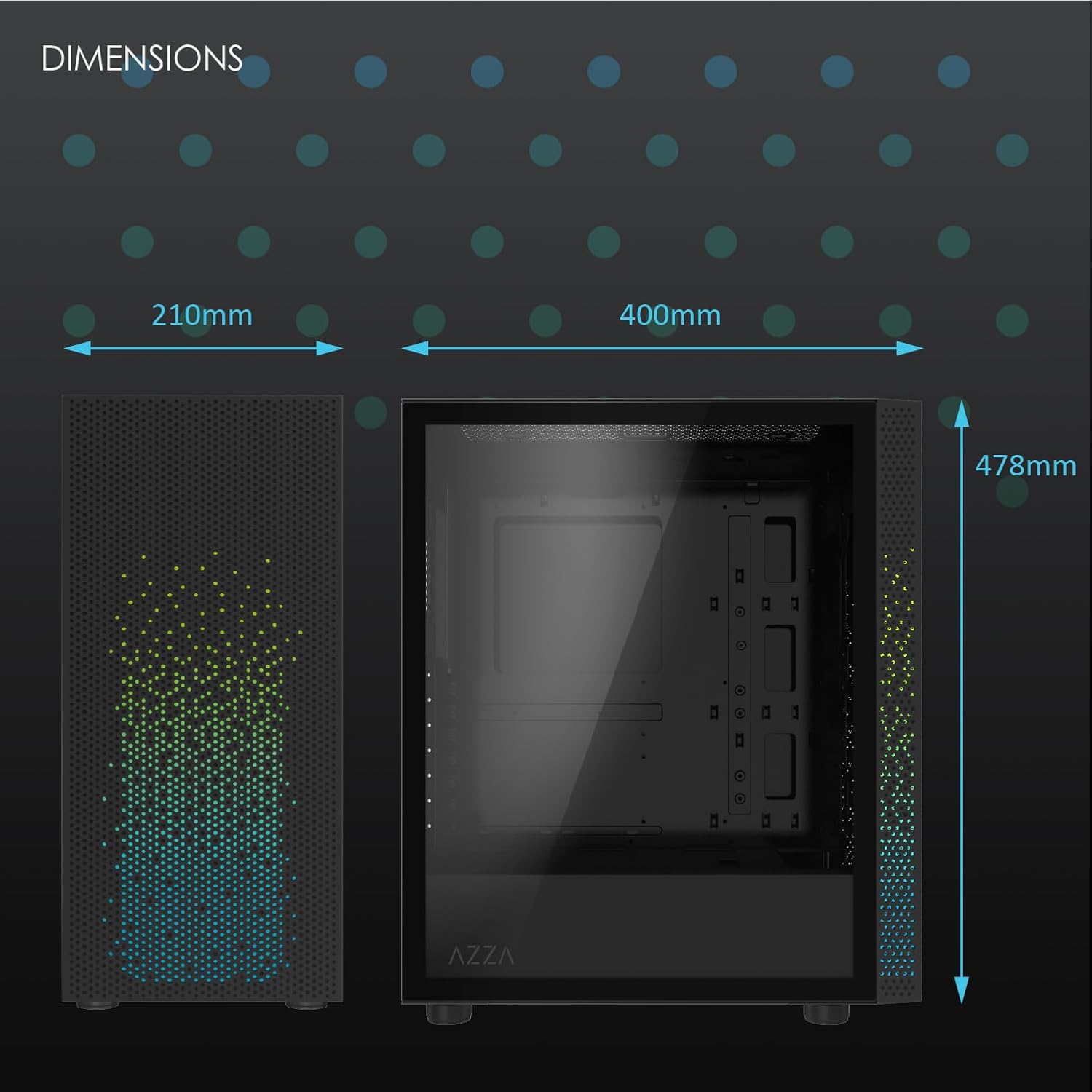
Abbildung 2: Physical dimensions of the AZZA CSAZ-340F CELESTA case: 210mm (width), 400mm (depth), 478mm (height).

Abbildung 3: Diagram illustrating fan and radiator mounting options for the AZZA CSAZ-340F CELESTA case, including front, top, and rear configurations.

Abbildung 4: Internal component support diagram for the AZZA CSAZ-340F CELESTA, showing maximum dimensions for CPU cooler, GPU, and PSU, along with drive bay locations.
5. Einrichtung und Installation
Follow these steps to install your components into the AZZA CSAZ-340F CELESTA case.
5.1 Vorbereitung des Falls
- Stellen Sie das Gehäuse auf eine ebene, stabile Oberfläche.
- Remove the side panels. Typically, these are secured with thumbscrews at the rear of the case.
5.2 Motherboard-Installation
- Install the I/O shield (if not pre-installed) into the rear opening of the case.
- Ensure the correct standoffs are installed for your ATX, Micro-ATX, or Mini-ITX motherboard. Adjust or add standoffs as needed using the provided tools.
- Setzen Sie das Motherboard vorsichtig auf die Abstandshalter und achten Sie dabei auf die Ausrichtung der Schraubenlöcher.
- Befestigen Sie das Motherboard mit den passenden Schrauben aus dem Zubehörkarton. Nicht zu fest anziehen.
5.3 Installation des Netzteils (PSU)
- Position the PSU in the bottom rear compartment of the case, ensuring the fan faces downwards (if there's a filtered vent) or upwards.
- Secure the PSU to the case with the provided screws from the rear.
- Verlegen Sie die benötigten Stromkabel durch die Kabeldurchführungen.
5.4 Installation des Speichermediums (HDD/SSD)
- 3.5"-Festplatten: Locate the drive cage. Slide the 3.5" HDDs into the drive trays and secure them, often tool-less or with screws.
- 2.5"-SSDs: Mount 2.5" SSDs to the dedicated mounting points on the motherboard tray or drive cage using screws.
- Connect SATA data and power cables to the installed drives.
5.5 Installation der Grafikkarte (GPU)
- Entfernen Sie die erforderlichen PCIe-Steckplatzabdeckungen von der Rückseite des Gehäuses.
- Carefully insert your graphics card into the appropriate PCIe slot on the motherboard until it clicks into place.
- Befestigen Sie die Grafikkarte mit Schrauben am Gehäuse.
- Connect any required PCIe power cables from the PSU to the graphics card.
5.6 Installation des CPU-Kühlers
Install your CPU cooler according to its specific manufacturer instructions. Ensure it does not exceed the maximum height of 165mm.
5.7 Lüfter- und Kühlerinstallation
Das Gehäuse unterstützt verschiedene Lüfter- und Radiatorkonfigurationen:
- Front: Up to 3 x 120mm or 3 x 140mm fans, or radiators up to 280mm/360mm.
- Spitze: Up to 2 x 120mm or 2 x 140mm fans, or 2 x 120mm radiators.
- Hinteren: 1 x 120mm fan (pre-installed) or 1 x 120mm radiator.
Mount fans and radiators using the appropriate screws and ensure proper airflow direction.
5.8 Kabelmanagement
Utilize the cable management cutouts and tie-down points behind the motherboard tray to route and secure cables. This improves airflow and aesthetics.
5.9 Endmontage
- Double-check all connections and ensure no cables are obstructing fans.
- Reattach the side panels.
- Connect external peripherals (monitor, keyboard, mouse, etc.) and the power cable.
6. Bedienung Ihres Systems
Once all components are installed and connected, you can power on your system. The front panel features power and reset buttons, along with USB and audio ports for convenient access.

Abbildung 5: Close-up of the AZZA CSAZ-340F CELESTA's front panel, highlighting the integrated lighting effects.
7. Wartung
- Staubfilter: Regularly clean the dust filters (if present) to maintain optimal airflow and cooling performance.
- Innenreinigung: Periodically open the case and use compressed air to remove dust from components and fans. Ensure the system is powered off and unplugged before cleaning.
- Außenreinigung: Wischen Sie die Außenflächen mit einem weichen, damp Tuch. Vermeiden Sie aggressive Chemikalien.
8. Fehlerbehebung
Sollten Probleme auftreten, beachten Sie die folgenden gängigen Schritte zur Fehlerbehebung:
- System schaltet sich nicht ein:
- Stellen Sie sicher, dass das Netzkabel sowohl mit dem Netzteil als auch mit der Steckdose fest verbunden ist.
- Check that the PSU switch is in the "ON" position.
- Verify all internal power connections (24-pin ATX, 8-pin CPU, PCIe power) are seated correctly.
- Confirm front panel power button cables are correctly connected to the motherboard.
- Keine Anzeigeausgabe:
- Stellen Sie sicher, dass Ihr Monitor an die Grafikkarte angeschlossen ist (nicht an die integrierten Grafikanschlüsse des Motherboards, es sei denn, Sie verwenden eine integrierte Grafikkarte).
- Setzen Sie die Grafikkarte wieder in ihren PCIe-Steckplatz ein.
- Überprüfen Sie die Eingangswahl des Monitors.
- Überhitzung:
- Verify all case fans are spinning and oriented correctly for airflow.
- Reinigen Sie alle Staubfilter und internen Bauteile.
- Ensure CPU cooler is properly seated and making good contact with the CPU.
9. Garantie und Support
Informationen zur Garantie und zum technischen Support finden Sie auf der offiziellen AZZA-Website. website or contact AZZA customer service directly. Keep your proof of purchase for warranty claims.
AZZA Offiziell WebWebsite: www.azza.com


