1. Produktüberschreitungview
The DALY BMS 8S 24V 200A LiFePO4 Battery Protection Module is designed to manage and protect 8-series LiFePO4 battery packs. It ensures safe and efficient operation by monitoring various parameters such as voltage, current, and temperature, providing essential protection functions.

Abbildung 1: Vorderseite view of the DALY BMS 8S 24V 200A module.
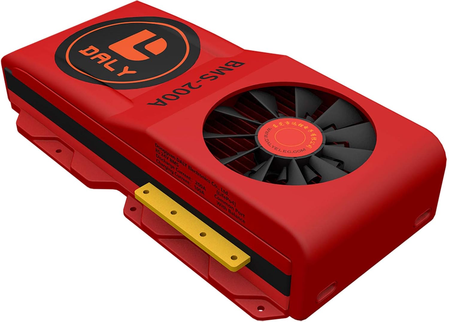
Abbildung 2: Schräg view of the DALY BMS 8S 24V 200A module.

Figure 3: DALY BMS 8S 24V 200A module showing connection ports.
2. Spezifikationen
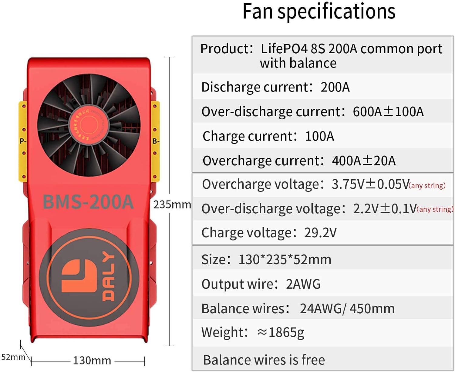
Figure 4: Fan specifications for the DALY BMS.
| Besonderheit | Wert |
|---|---|
| Technische Daten | 4.72 x 9.25 x 2.05 Zoll |
| Artikelgewicht | 4.11 Pfund (1865 Gramm) |
| Eingangslautstärketage | 24 Volt (DC) |
| Marke | DALY |
| Hersteller | Dongguan Daly Electronics Co., Ltd |
| Farbe | Mehrfarbig |
Detailed Product Parameters (LiFePO4 8S BMS)

Figure 5: Part 1 of the detailed product parameters for LiFePO4 8S BMS.

Figure 6: Part 2 of the detailed product parameters for LiFePO4 8S BMS.
Detailed Product Parameters (LiFePO4 8S Smart BMS)

Figure 7: Part 1 of the detailed product parameters for LiFePO4 8S Smart BMS.

Figure 8: Part 2 of the detailed product parameters for LiFePO4 8S Smart BMS.
3. Produktstruktur
The DALY BMS is engineered with multiple layers for optimal performance and protection. Key components include:
- Insulated Flame-Retardant Shell: Provides external protection and safety.
- Smart and Powerful Fan: Ensures efficient cooling to maintain optimal operating temperatures.
- Pure Aluminum Heat Sink: Dissipates heat effectively from internal components.
- High Current Copper Plate: Features a 3mm pure copper interface for robust current handling.
- DALY BMS Control Board: The core intelligence for battery management and protection.
- Thermal Conductive Compound: Enhances heat transfer between components and heat sinks.
- Insulation Fixing Plate: Secures and insulates internal components.

Abbildung 9: Explosionsdarstellung view illustrating the internal structure of the DALY BMS.
4. Verdrahtungsanweisungen
Proper wiring is critical for the safe and correct operation of your DALY BMS. Please follow these steps carefully. Tools needed: soldering machine (suggested 662°F/350°C), scissors, double-sided tape, tin wire, multimeter.
4.1. Preparation and SampBestimmung des Ling-Punktes
Before starting, ensure you have all necessary tools and materials. The sampling points on your battery pack must be correctly identified and marked. For a 10-battery series (e.g., 8S LiFePO4), there will be 11 sampling points, including the total negative (B-) and total positive (B+) terminals.
Video 1: Guide on preparing materials and determining sampling points for DALY BMS wiring.
Video 2: Detailed instructions on how to determine the correct sampling points for DALY BMS.
4.2. Balance Lead Connection
Notiz: Du muss disconnect balance wires end and BMS connection port before welding black and red balance wires on the battery pack.
- After assembling your LiFePO4 battery pack, mark battery B-, B1, B2,..., until battery pack B+.
- Fix balance wires on the battery pack where the black wire can reach battery pack B-. The 1st red wire can reach B1, 2nd red wire can reach B2,..., until the last red wire can reach battery pack B+ with double-sided tape.
- Cut off excess length with scissors, welding the black wire's end at Battery pack B-, welding the 1st red wire's end at B1, 2nd red wire's end at B2,..., until the last red wire's end at Battery pack B+.
- Measure balance wires white end's 2 neighboring metal points voltage; if voltagDer Spannungsbereich liegt zwischen 2.0 V und 3.6 V, das bedeutet, dass die Verkabelung korrekt ist.
- Connect balance wires white end with BMS connection port, use multimeter ohm detection function and turn on the buzzer; connect multimeter's black test pen with BMS P- and multimeter's red test pen with BMS B-, when there is beep sound, the BMS circuit conduction is OK and continue.
- Verwenden Sie ein Multimeter mit Gleichspannungsmessung.tage Funktion zur Messung des Volumens des Akkupackstage (zwischen Batterie B- und Batterie B+) und über die BMS-Ausgangsspannungtage (between BMS B- and Battery B+), if they are the same voltage, das BMS kann bereits normal funktionieren und das BMS reparieren, um einen schlechten Kontakt aufgrund starker Vibrationen während des Gebrauchs zu vermeiden.

Figure 10: Diagram illustrating the balance lead wiring process for the DALY BMS.
Video 3: Step-by-step guide on soldering DALY BMS wires to the battery pack.
5. Common Wiring Errors and Troubleshooting
Incorrect wiring can lead to serious issues, including damage to the BMS or battery pack. Be aware of these common errors:
- Falscher Kabelbaum: Using a wiring harness not specifically designed or compatible with your DALY BMS model can cause connection issues, poor contact, or even short circuits. Always use the provided or recommended wiring.
- Einbau des BMS vor der Verkabelung: Never insert the BMS connection port before all balance wires are correctly soldered and verified. Doing so can cause immediate damage to the BMS due to voltage spikes or incorrect current paths.
- Virtual Welding/Poor Solder Joints: Inadequate soldering can result in poor electrical contact, leading to voltage drops, overheating, and unreliable performance. Ensure all solder joints are strong and secure.
- No Inspection After Wiring: Failing to inspect and verify all connections and voltages with a multimeter after wiring but before connecting the BMS can lead to catastrophic failure. Always check individual cell voltages and the overall pack voltage.
- Falsche P- und B-Leitungsverbindung: The P- line (output/charge negative) and B- line (total battery negative) must be connected correctly. Reversing these or connecting them improperly can cause short circuits within the protective plate, burn out sampling lines, or damage the entire protective plate.
Video 4: Explanation of 5 common wiring errors to avoid when installing DALY BMS.
6. Anwendungen
DALY BMS modules are versatile and suitable for a wide range of applications requiring robust battery management. These include:
- Two-wheelers (e.g., electric bikes, scooters)
- AGV Forklifts
- Elektroroller
- Photovoltaic Energy Storage Systems
- Energiespeichersysteme für Wohnmobile
- Energiespeichersysteme für Zuhause

Figure 11: Visual representation of various applications for DALY BMS products.

Abbildung 12: Bspample of a DALY BMS in an energy storage application with mobile app monitoring.
7. Sicherheitsvorkehrungen
- Always wear appropriate personal protective equipment (PPE) when handling batteries and performing wiring.
- Stellen Sie sicher, dass alle Verbindungen sicher und isoliert sind, um Kurzschlüsse zu vermeiden.
- Do not attempt to modify the BMS or battery pack beyond the instructions provided.
- Keep the BMS and battery pack away from moisture, heat, and flammable materials.
- In case of any malfunction or unusual behavior, disconnect the battery pack immediately and seek professional assistance.
8. Garantie und Support
For warranty information, technical support, or any inquiries regarding your DALY BMS, please refer to the official DALY website or contact your authorized dealer. Ensure you retain your proof of purchase for warranty claims.


