1. Einleitung
This manual provides detailed instructions for the safe and effective use of the IDEAL Electrical 61-327 600V Manual Range Multimeter. This device is designed for measuring AC/DC voltage, resistance, continuity, diodes, and testing batteries. It is a CAT III 600V rated instrument suitable for various electrical testing applications.

Abbildung 1.1: Front view of the IDEAL Electrical 61-327 Multimeter. This image displays the multimeter's main display, rotary dial, function buttons, and input jacks for test leads.
2. Sicherheitshinweise
WARNUNG: To avoid electric shock or personal injury, read, understand, and follow all safety information and instructions before using this multimeter. Keep this manual for future reference.
- Vergewissern Sie sich vor Gebrauch stets, dass das Multimeter einwandfrei funktioniert. Prüfen Sie die Messleitungen auf Beschädigungen.
- Nicht mehr als die angegebene Menge auftragen.tage, wie auf dem Zähler angegeben, zwischen den Klemmen oder zwischen einer beliebigen Klemme und Masse.
- Seien Sie vorsichtig beim Arbeiten mit VolumentagEs liegt über 30 V AC RMS, 42 V Spitze oder 60 V DC. Diese SpannungentagEs besteht die Gefahr eines Stromschlags.
- Trennen Sie stets die Stromzufuhr zum Stromkreis und entladen Sie alle Hochspannungsgeräte.tage Kondensatoren, bevor Sie Widerstand, Durchgang oder Dioden testen.
- Do not operate the meter with the case open or the battery cover removed.
- Tauschen Sie die Batterien sofort aus, sobald die Anzeige für niedrigen Batteriestand erscheint, um genaue Messwerte zu gewährleisten.
- This multimeter is rated for CAT III 600V. Do not use it in environments exceeding this rating.
3. Produktmerkmale
The IDEAL Electrical 61-327 Multimeter offers a range of features designed for electrical professionals:
- UL Certified CAT III 600V: Ensures safety and reliability for AC/DC manual range measurements.
- Messmöglichkeiten: Misst AC/DC-Voltage, resistance, continuity, diodes, and tests batteries.
- Kontaktloses Volumentage (NCV) Sensorik: Erkennt AC-Voltage ohne direkten Kontakt, wodurch die Sicherheit erhöht wird.
- Display mit Hintergrundbeleuchtung: Improves visibility in poorly lit environments.
- Built-in Probe Tip Holders: Allows for convenient and safer measurement by securing one lead.
- Hanging Strap Clip: Compatible with IDEAL hanging straps (sold separately, e.g., UMHS-757) for hands-free operation.
- Rugged Overmolding: Enhances grip and provides drop protection.
- Hold-Funktion: Freezes the displayed reading for easier recording.
- Selectable Auto Power Off: Verlängert die Batterielebensdauer.
4. Komponenten und Bedienelemente
Familiarize yourself with the main components and controls of your multimeter:

Abbildung 4.1: Front view of the multimeter, highlighting the display, rotary switch, and function buttons. The display shows measurement values and indicators. The rotary switch selects measurement functions. Buttons include HOLD and Backlight.

Abbildung 4.2: Included test leads and AAA batteries. The red and black test leads are essential for making electrical measurements. The batteries power the device.

Abbildung 4.3: Hinteren view of the multimeter, showing the battery compartment cover and safety warnings. This view also illustrates the integrated test lead storage points.
5. Einrichtung
5.1 Einlegen der Batterie
The multimeter requires three (3) 1.5V AAA batteries for operation. To install or replace batteries:
- Stellen Sie sicher, dass das Multimeter ausgeschaltet ist.
- Suchen Sie das Batteriefach auf der Rückseite des Messgeräts (siehe Abbildung 4.3).
- Verwenden Sie einen Schraubendreher, um die Schraube zu lösen, mit der die Batterieabdeckung befestigt ist.
- Entfernen Sie die Batterieabdeckung.
- Insert three new 1.5V AAA batteries, observing the correct polarity (+/-) as indicated inside the compartment.
- Bringen Sie die Batterieabdeckung wieder an und ziehen Sie die Schraube fest an.
5.2 Anschließen der Testleitungen
Always connect the black test lead to the "COM" (Common) input jack. Connect the red test lead to the "VΩ" input jack for voltage, resistance, continuity, and diode measurements. Ensure connections are firm.
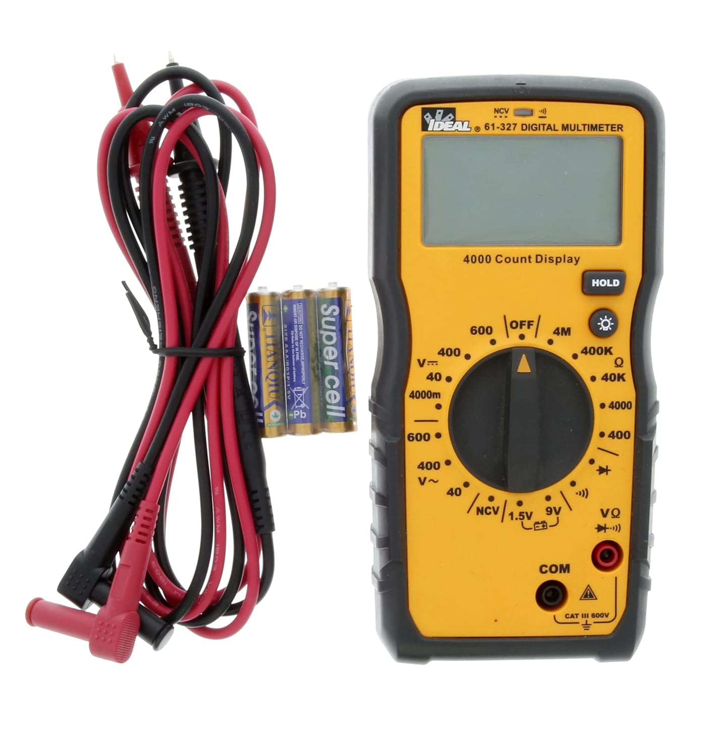
Abbildung 5.1: The multimeter shown with its test leads and batteries, ready for initial setup. The black lead connects to COM, and the red lead connects to VΩ.
6. Bedienungsanleitung
This section details how to perform various measurements using the 61-327 Multimeter.
6.1 Messen von AC/DC-Voltage
- Drehen Sie den Drehschalter auf die gewünschte Wechselstromspannung.tage (V~) oder DC Voltage (V=) Bereich. Wählen Sie einen Bereich, der höher als das erwartete Volumen ist.tage.
- Connect the black test lead to the "COM" jack and the red test lead to the "VΩ" jack.
- Schließen Sie die Messspitzen parallel an den Stromkreis oder das Bauteil an, das Sie messen möchten.
- Lesen Sie den Bandtage-Wert auf dem Display.
6.2 Widerstandsmessung (Ω)
- WARNUNG: Vor der Widerstandsmessung muss sichergestellt werden, dass der Stromkreis stromlos ist und alle Kondensatoren entladen sind.
- Turn the rotary switch to the desired Resistance (Ω) range.
- Connect the black test lead to the "COM" jack and the red test lead to the "VΩ" jack.
- Schließen Sie die Messspitzen an das Bauteil an, an dem der Widerstand gemessen werden soll.
- Lesen Sie den Widerstandswert auf dem Display ab.
6.3 Durchgangstest
- WARNUNG: Vor der Durchführung eines Durchgangstests muss sichergestellt werden, dass der Stromkreis spannungsfrei ist.
- Turn the rotary switch to the Continuity (•))) position.
- Connect the black test lead to the "COM" jack and the red test lead to the "VΩ" jack.
- Berühren Sie mit den Prüfspitzen die beiden Punkte, die Sie auf Durchgang prüfen möchten.
- Ein akustisches Signal signalisiert Durchgang (niedriger Widerstand). Der Widerstandswert wird im Display angezeigt.
6.4 Diodentest
- WARNUNG: Vor der Durchführung eines Diodentests muss sichergestellt werden, dass der Stromkreis spannungsfrei ist.
- Drehen Sie den Drehschalter in die Diodenposition (→|).
- Connect the black test lead to the "COM" jack and the red test lead to the "VΩ" jack.
- Schließen Sie die rote Prüfspitze an die Anode und die schwarze Prüfspitze an die Kathode der Diode an.
- Das Display zeigt die Vorwärtslautstärke an.tage drop. Vertauschen Sie die Messspitzen; die Anzeige sollte bei einer intakten Diode „OL“ (Open Loop) anzeigen.
6.5 Battery Test (1.5V / 9V)
- Turn the rotary switch to the 1.5V or 9V battery test position.
- Connect the black test lead to the "COM" jack and the red test lead to the "VΩ" jack.
- Connect the red test probe to the positive terminal of the battery and the black test probe to the negative terminal.
- Lesen Sie das Batterievolumentage auf dem Display.
6.6 Berührungslose Voltage (NCV) Sensorik
Die NCV-Funktion ermöglicht die Erkennung von Wechselstromspannungen.tage ohne direkten Kontakt mit Leitern.
- Drehen Sie den Drehschalter auf die Position NCV.
- Move the top tip of the multimeter near the conductor or outlet to be tested.
- The meter will emit an audible tone and an illuminated red LED will flash when AC voltage is detected. The display may show "EF" or similar indication.

Abbildung 6.1: The multimeter being used to perform a Non-Contact Voltage (NCV) test near an electrical outlet. The display shows "EF" indicating voltage Erkennung.
6.7 Verwendung der HOLD-Funktion
Drücken Sie die Taste „HOLD“, um den aktuellen Messwert auf dem Display einzufrieren. Drücken Sie sie erneut, um die Speicherung aufzuheben und die Live-Messungen fortzusetzen.
6.8 Verwenden der Hintergrundbeleuchtung
Press the backlight button (light bulb icon) to illuminate the display for better visibility in dark conditions. Press it again to turn off the backlight.
7. Wartung
7.1 Reinigung
Den Zähler mit Werbung abwischenamp Mit einem Tuch und mildem Reinigungsmittel reinigen. Keine Scheuermittel oder Lösungsmittel verwenden. Vor Gebrauch sicherstellen, dass das Messgerät vollständig trocken ist.
7.2 Batteriewechsel
Refer to Section 5.1 for instructions on battery installation and replacement. Always replace all three AAA batteries at the same time.
7.3 Prüfung der Testleitungen
Regularly inspect test leads for any signs of damage, such as cuts, cracks, or frayed insulation. Replace damaged leads immediately to prevent electric shock.
8. Fehlerbehebung
| Problem | Mögliche Ursache | Lösung |
|---|---|---|
| Das Messgerät lässt sich nicht einschalten. | Defekte oder falsch eingesetzte Batterien. | Check battery polarity; replace batteries (refer to Section 5.1). |
| „OL“ (Überlastung) wird angezeigt. | Messwert überschreitet den gewählten Bereich oder Stromkreis ist unterbrochen. | Select a higher range or check for an open circuit in the component/wiring. |
| Ungenaue Messwerte. | Low battery, incorrect range selection, or damaged test leads. | Replace batteries, select appropriate range, inspect and replace test leads if damaged. |
| No continuity tone. | Unterbrechung oder hoher Widerstand. | Verify the circuit is closed; check for breaks in wiring or components. |
9. Spezifikationen
Key technical specifications for the IDEAL Electrical 61-327 Multimeter:
- Modellnummer: 61-327
- Messart: Manual Range Digital Multimeter
- Sicherheitsbewertung: UL certified CAT III 600V AC/DC
- AC-Lautstärketage: Bis zu 600V
- DC-Voltage: Bis zu 600V
- Widerstand: Up to 4MΩ (4000kΩ)
- Kontinuität: Audible tone and resistance display
- Diodentest: Ja
- Batterietest: 1.5V, 9V
- Kontaktloses Volumentage (NCV): Ja
- Anzeige: Backlit, 4000 Count
- Energiequelle: 3 x 1.5 V AAA-Batterien
- Automatisches Ausschalten: Wählbar
- Hold-Funktion: Ja
- Abmessungen: Ungefähr 9.09 x 6.18 x 3.35 Zoll
- Gewicht: Ungefähr 1.1 Pfund
- Farbe: Gelb
- Hersteller: Ideal Industries

Abbildung 9.1: A comparison table of various IDEAL digital multimeters, including the 61-327, detailing their features and specifications. This table provides a quick overview of the 61-327's capabilities relative to other models.
10. Garantie und Support
For warranty information, technical support, or service inquiries, please contact IDEAL Industries directly. Refer to the official IDEAL webDie aktuellsten Kontaktdaten finden Sie auf der Website oder der Produktverpackung.
Additional resources, including a downloadable PDF user manual, may be available on the IDEAL Store on Amazon oder dem offiziellen Hersteller webWebsite.


