1. Einleitung
This manual provides detailed instructions for the installation, operation, and maintenance of the Supermicro X13SEI-F Server Motherboard. This motherboard is designed for high-performance server applications, supporting Intel Xeon processors with an LGA4677 socket and DDR5 memory.
Please read this manual thoroughly before attempting to install or operate the motherboard to ensure proper setup and to prevent damage to the components.
2. Sicherheitshinweise
Beachten Sie die folgenden Sicherheitsvorkehrungen, um Verletzungen und Schäden am Gerät zu vermeiden:
- Vor dem Ein- oder Ausbau von Bauteilen muss immer das Netzkabel vom Netzteil getrennt werden.
- Wear an anti-static wrist strap when handling the motherboard and other components to prevent electrostatic discharge (ESD).
- Ensure the installation environment is dry and free from static electricity.
- Das Motherboard darf weder Feuchtigkeit noch extremen Temperaturen ausgesetzt werden.
- Fassen Sie das Motherboard an den Kanten an, um eine Berührung empfindlicher Bauteile zu vermeiden.
- Beachten Sie die spezifischen Sicherheitshinweise zum Umgang mit Stromanschlüssen in der Bedienungsanleitung des Netzteils.
3. Packungsinhalt
Verify that all items are present and in good condition. If any items are damaged or missing, contact your vendor.
- Supermicro X13SEI-F Server Motherboard
- E / A-Schild
- SATA-Kabel (Anzahl kann variieren)
- Quick Reference Guide / User Manual (this document)
- Driver CD/DVD or USB drive (or download instructions)
4. Produktüberschreitungview
The Supermicro X13SEI-F is a high-performance server motherboard featuring the LGA4677 socket, designed to support Intel Xeon Scalable processors. It offers robust memory capabilities with 8 DDR5 DIMM slots, supporting up to 4800MHz memory speed. The board also includes multiple PCIe slots for expansion.
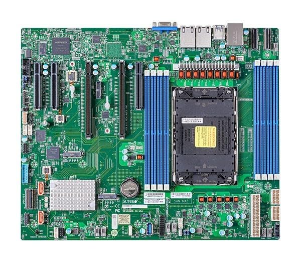
Figure 1: Supermicro X13SEI-F Server Motherboard. This image displays the overall layout of the motherboard, including the CPU socket, DIMM slots, and various connectors.
4.1 Hauptmerkmale
- CPU-Sockel: LGA4677 for Intel Xeon Scalable Processors
- Chipsatz: Intel C621
- Erinnerung: 8x DDR5 DIMM slots, up to 4800MHz
- Erweiterungssteckplätze: Multiple PCIe slots (specific configuration depends on model variant)
- Lagerung: Support for various storage interfaces (SATA, NVMe - specific details in specifications)
- Vernetzung: Integrated LAN controllers
5. Einrichtung und Installation
Before beginning installation, ensure your system case is compatible with the motherboard's form factor and that you have all necessary components.
5.1 CPU-Installation (LGA4677)
- Suchen Sie den LGA4677-Sockel auf dem Motherboard.
- Carefully open the CPU socket retention mechanism according to the instructions provided with your CPU or motherboard.
- Align the CPU with the socket, ensuring the triangular mark on the CPU matches the mark on the socket. Do not force the CPU into the socket.
- Senken Sie die CPU vorsichtig in den Sockel ab.
- Close the CPU socket retention mechanism until it locks securely.
- Installieren Sie den CPU-Kühler gemäß den Anweisungen des Herstellers.
5.2 RAM-Installation (DDR5)
- Locate the 8 DDR5 DIMM slots on the motherboard.
- Öffnen Sie die Halteklammern an beiden Enden des DIMM-Steckplatzes.
- Richten Sie die Kerbe am DDR5-Speichermodul an der entsprechenden Aussparung im DIMM-Steckplatz aus.
- Insert the memory module firmly into the slot until the retention clips snap into place. Ensure both clips are closed.
- For optimal performance, refer to the motherboard's manual for recommended memory population order.
5.3-Zoll-PCIe-Karteninstallation
- Identify the appropriate PCIe slot for your expansion card (e.g., GPU, RAID card).
- Entfernen Sie die entsprechende Erweiterungssteckplatzabdeckung von Ihrem Gehäuse.
- Align the PCIe card with the slot and press down firmly until it is fully seated.
- Befestigen Sie die Karte mit einer Schraube oder einem Halteclip am Gehäuse.
5.4 Installation des Speichergeräts
- SATA-Laufwerke: Connect SATA data cables from the motherboard's SATA ports to your SATA hard drives or SSDs. Connect power cables from the PSU to the drives.
- NVMe M.2 Drives: Locate the M.2 slots. Insert the M.2 drive at an angle, then push it down and secure it with the provided screw or retention mechanism.
5.5 Stromanschlüsse
- Verbinden Sie den 24-poligen ATX-Stromanschluss Ihres Netzteils mit der Hauptstrombuchse auf dem Motherboard.
- Connect the 8-pin (or 4+4 pin) EPS 12V CPU power connector(s) to the corresponding sockets near the CPU.
- Stellen Sie sicher, dass alle Stromanschlüsse fest sitzen.
5.6 Anschlüsse an der Vorderseite
Connect the front panel cables (Power LED, HDD LED, Power Switch, Reset Switch, USB, Audio) from your chassis to the corresponding headers on the motherboard. Refer to the motherboard's silkscreen labels or the detailed manual for exact pin configurations.
6. Bedienungsanleitung
6.1 Erster Start
- After completing all hardware installations, connect the monitor, keyboard, and mouse.
- Connect the power cord to the power supply and turn on the power switch on the PSU.
- Drücken Sie den Netzschalter an Ihrem Gehäuse.
- The system should power on, and you should see the BIOS/UEFI POST screen.
6.2 BIOS/UEFI-Einrichtung
Um das BIOS/UEFI-Setup-Dienstprogramm aufzurufen, drücken Sie die Taste DEL or F2 key repeatedly during the POST process. Within the BIOS/UEFI, you can configure:
- Startreihenfolge
- Systemzeit und Datum
- CPU and memory settings
- Storage configurations (RAID, AHCI)
- Regelung der Lüftergeschwindigkeit
- Sicherheitseinstellungen
Save changes before exiting the BIOS/UEFI.
6.3 Installation des Betriebssystems
Insert your operating system installation media (USB drive or DVD) and set it as the primary boot device in the BIOS/UEFI. Follow the on-screen instructions to install your preferred operating system. After installation, install all necessary drivers from the Supermicro webWebsite oder die bereitgestellten Treibermedien.
7. Wartung
7.1 Reinigung
- Regularly clean dust from the motherboard and system components using compressed air.
- Vor der Reinigung sicherstellen, dass das System ausgeschaltet und vom Stromnetz getrennt ist.
- Vermeiden Sie es, flüssige Reinigungsmittel direkt auf Bauteile aufzutragen.
7.2 Firmware-Updates
Überprüfen Sie regelmäßig das Supermicro. website for updated BIOS/UEFI firmware. Firmware updates can improve system stability, performance, and compatibility. Follow the specific instructions provided by Supermicro for updating the firmware to avoid system damage.
8. Fehlerbehebung
Dieser Abschnitt bietet Lösungen für häufig auftretende Probleme.
8.1 Kein Strom / Kein POST (Selbsttest beim Einschalten)
- Stromanschlüsse prüfen: Ensure the 24-pin ATX and 8-pin EPS 12V power connectors are securely seated.
- Netzteil prüfen: Testen Sie das Netzteil mit einem anderen System oder einem Netzteiltester.
- Komponenten neu einsetzen: Setzen Sie die CPU, die RAM-Module und alle Erweiterungskarten neu ein.
- CMOS löschen: Refer to the motherboard manual for instructions on how to clear the CMOS (Complementary Metal-Oxide-Semiconductor) settings, which can resolve boot issues.
- Mindestkonfiguration: Try booting with only the CPU, one RAM stick, and the necessary power connections.
8.2 Keine Displayausgabe
- Monitorverbindung: Ensure the monitor is properly connected to the graphics output (either integrated or discrete GPU) and is powered on.
- Grafikkarte: If using a discrete graphics card, ensure it is fully seated in its PCIe slot and has all necessary power connectors from the PSU.
- Integrierte Grafik: If your CPU supports integrated graphics, try connecting the monitor to the motherboard's video output to rule out a discrete GPU issue.
8.3 Betriebssystem startet nicht
- Reihenfolge der Stiefel: Check the BIOS/UEFI settings to ensure the correct boot device (e.g., SSD, HDD) is selected as the primary boot option.
- Drive Connections: Verify that your storage drives are properly connected (data and power).
- Betriebssysteminstallation: If the OS is newly installed, ensure the installation process completed successfully and all drivers are installed.
9. Spezifikationen
| Besonderheit | Detail |
|---|---|
| Marke | Supermicro |
| Modellname | MBD-X13SEI-F-B |
| CPU-Sockel | LGA 4677 |
| Kompatible Prozessoren | Intel Xeon Scalable |
| Chipsatztyp | Intel C621 |
| RAM-Speichertechnologie | DDR5 |
| Speichergeschwindigkeit | 4800 MHz |
| RAM-Steckplätze | 8x DDR5 DIMM slots |
| Produktabmessungen (L x B x H) | 16 x 12 x 5 Zoll |
| Artikelgewicht | 3.19 Pfund |
| Erstes verfügbares Datum | 20. Januar 2023 |
Hinweis: Technische Daten können sich ohne vorherige Ankündigung ändern. Aktuelle Informationen finden Sie auf der offiziellen Supermicro-Produktseite.
10. Garantie und technischer Support
10.1 Garantieinformationen
Supermicro products are covered by a limited warranty. For detailed warranty terms and conditions, including duration and coverage, please visit the official Supermicro website or consult the warranty card included with your product. Keep your proof of purchase for warranty claims.
10.2 Technischer Support
For technical assistance, driver downloads, BIOS updates, and further product information, please visit the official Supermicro support webWebsite:
https://www.supermicro.com/support
Before contacting support, please have your motherboard model number (MBD-X13SEI-F-B) and serial number ready.