1. Einleitung
This manual provides essential instructions for the safe and efficient operation of your Irfora Smart WiFi Circuit Breaker. Please read this manual thoroughly before installation and use, and retain it for future reference.
The Irfora Smart WiFi Circuit Breaker allows for remote control and monitoring of electrical appliances via a mobile application. It integrates various timing functions, including timer, countdown, and loop timing, to enhance home automation. Constructed with flame-retardant PA66 material, the device ensures safe operation. Users can adjust appliance switching states, monitor real-time load conditions, and view detailed electrical data such as current, voltage, power, and energy consumption. The device also supports integration with smart voice assistants for convenient hands-free control.
2. Sicherheitshinweise
WARNUNG: Electrical installation should only be performed by qualified personnel. Failure to follow these instructions can result in electric shock, fire, or serious injury.
- Vor jeglichen Installations- oder Wartungsarbeiten muss die Stromzufuhr am Hauptsicherungsschalter unterbrochen werden.
- Ensure the device is installed in a dry environment, away from moisture and direct sunlight.
- Überprüfen Sie, ob das Volumentage and current ratings of the circuit breaker match your electrical system requirements.
- Do not attempt to repair or modify the device. Contact qualified service personnel for assistance.
- Halten Sie Kinder von elektrischen Anlagen fern.
3. Produktüberschreitungview
The Irfora Smart WiFi Circuit Breaker is designed for DIN rail mounting and features a compact design with integrated WiFi connectivity for smart home integration.
3.1 Komponenten

Abbildung 1: Front view of the Irfora Smart WiFi Circuit Breaker. This image displays the main unit with its signal light, power button, and metering label, along with the N and L terminals at the top and bottom for wiring.
- Signallicht: Indicates network status and pairing mode.
- Netzschalter: Manual control for ON/OFF.
- Metering Label: Indicates energy metering capability.
- Terminals (N, L): For connecting neutral and live wires.
3.2 Hauptmerkmale

Abbildung 2: Überview of the smart features including Remote Control, Voice Control, Timing Mode, Countdown Mode, Loop Timing, and Real-time monitoring of electricity consumption.
- Fernbedienung: Manage your appliances from anywhere via the mobile app.
- Sprachsteuerung: Compatible with smart voice assistants for hands-free operation.
- Mehrere Timing-Modi:
- Timing-Modus: Schedule specific ON/OFF times (e.g., turn on lights at 6:30 PM).
- Countdown-Modus: Set a countdown for the device to turn OFF (e.g., turn off lights after 10 minutes).
- Schleifen-Timing: Set recurring ON/OFF cycles (e.g., turn on at 6:00 AM, turn off at 8:00 AM daily).
- Echtzeitüberwachung: View aktuell, voltage, power, and energy consumption data.
- Sicherheit: Constructed with flame-retardant PA66 material.
- Einfache Installation: Designed for DIN rail mounting with secure tunnel-type wiring ports.
4. Spezifikationen

Abbildung 3: Dimensions of the circuit breaker, showing a width of 18mm, height of 82mm, and depth of 50mm.
| Parameter | Wert |
|---|---|
| Marke | Ifora |
| Modell | 40A (TYHDEE22496-5) |
| Nennstrom | 40A (Other variants: 10A, 16A, 25A, 32A, 63A) |
| Stöcke | 1P+N (N-Pole pass-through) |
| Nennbetriebsvoltage Reichweite | 90 V bis 240 V |
| Material | ABS, Flame-retardant PA66 |
| Abmessungen (L x B x H) | 8.5 x 6 x 3 cm (Product) / 18mm x 82mm x 50mm (Device) |
| Paketgewicht | 125g |
| Ursprungsland | China |
5. Einrichtung
5.1 Installation
- Stromabschaltung: Before installation, ensure the main power supply to the circuit is completely disconnected at the distribution board.
- Montage: Mount the Irfora Smart WiFi Circuit Breaker onto a standard DIN rail within your electrical panel.
- Verdrahtung: Connect the live (L) and neutral (N) wires to the corresponding terminals on the circuit breaker. Ensure all connections are secure. The device features single-channel wiring with tunnel-type wiring ports for enhanced security.
- Wiederherstellung der Stromversorgung: Sobald die Verkabelung abgeschlossen und überprüft ist, schalten Sie die Stromversorgung des Stromkreises wieder ein.

Abbildung 4: Close-up showing the touch handle, flame-retardant material, single-channel wiring ports, and positioning clip for easy installation.
5.2 App-Pairing
- Lade App herunter: Download the compatible mobile application (e.g., Tuya Smart or Smart Life) from your smartphone's app store.
- Registrieren/Anmelden: Öffne die App und registriere ein neues Konto oder melde dich an, falls du bereits eines hast.
- Gerät hinzufügen: Follow the in-app instructions to add a new device. Typically, this involves selecting "Electrical" or "Circuit Breaker" from the device list.
- Verbindungsmodus: Put the circuit breaker into pairing mode. Refer to the LED indicator description for pairing mode status. The LED indicator will show blue flashing slowly when in pairing mode.
- Mit Netzwerk verbinden: Ensure your smartphone is connected to a 2.4GHz WiFi network. Enter your WiFi password in the app to connect the device.
- Bestätigung: Once successfully connected, the LED indicator on the circuit breaker will change from a slow blue flash to a steady blue light. The app will also confirm the device has been added.

Abbildung 5: Screenshot of the mobile application interface, illustrating the device connection process and real-time display of electrical parameters like power, voltage, current, and energy consumption.
6. Bedienungsanleitung
6.1 Manuelle Steuerung
Press the physical power button on the circuit breaker to manually turn the connected circuit ON or OFF. The button indicator will show a light up when the switch is OFF and a light out when the switch is ON.
6.2 App-Fernsteuerung
Open the mobile application. From the device interface, you can remotely turn the circuit breaker ON or OFF. You can also monitor the real-time status of connected electrical loads.
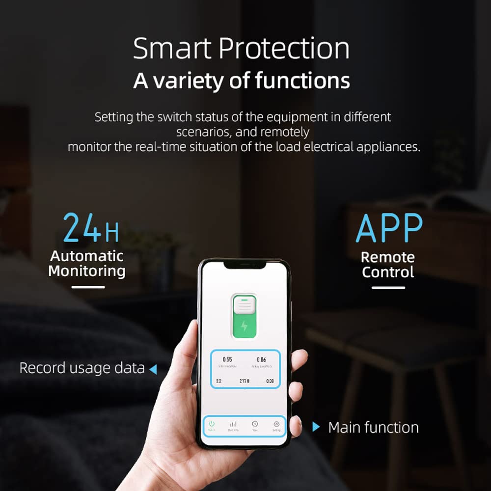
Abbildung 6: The mobile app allows for remote control, 24-hour automatic monitoring, and recording of usage data for smart protection and various functions.
6.3 Echtzeitüberwachung
The app provides real-time data on your electrical consumption. You can view:
- Strom (A)
- Bandtage (V)
- Leistung (W)
- Gesamtenergieverbrauch (kWh)
- Daily Energy Consumption (kWh)
Historical data can also be accessed, allowing you to monitor usage over different periods (year, month, day, hour).
6.4 Zeitmodi
Utilize the app to set up various timing schedules for automated control of your appliances.

Abbildung 7: Visual representation of the three timing modes: Timing Mode (e.g., turn on lights at 6:30 PM), Countdown Mode (e.g., turn off lights after 10 minutes), and Loop Timing (e.g., turn on at 6:00 AM, turn off at 8:00 AM).
- Timing-Modus: Set a specific time for the device to turn ON or OFF. For example, schedule lights to turn on at 6:30 PM before you arrive home.
- Countdown-Modus: Set a duration after which the device will turn OFF. For example, turn off lights 10 minutes after you fall asleep.
- Schleifen-Timing: Create recurring ON/OFF cycles. For example, turn on lights at 6:00 AM and turn them off at 8:00 AM daily.
6.5 Sprachsteuerung
Integrate the circuit breaker with compatible smart home assistants (e.g., Amazon Alexa, Google Assistant) to control it using voice commands. Refer to your smart assistant's setup guide for integration instructions.
7. Wartung
- Überprüfen Sie das Gerät regelmäßig auf Anzeichen von Beschädigungen oder lockeren Verbindungen.
- Halten Sie das Gerät sauber und staubfrei. Verwenden Sie zum Reinigen ein trockenes, weiches Tuch.
- Verwenden Sie keine flüssigen Reinigungs- oder Lösungsmittel.
- Sorgen Sie für eine ausreichende Belüftung rund um das Gerät, um eine Überhitzung zu vermeiden.
8. Fehlerbehebung
| Problem | Mögliche Ursache | Lösung |
|---|---|---|
| Gerät stellt keine Verbindung zum WLAN her. | Incorrect WiFi password, 5GHz network, device too far from router, device not in pairing mode. |
|
| Das Gerät reagiert nicht auf App-Befehle. | No internet connection, device offline, app malfunction. |
|
| Inaccurate power monitoring data. | Improper wiring, device malfunction. |
|
8.1 LED Indicator Description (TO-Q-SY1-JWT)

Abbildung 8: Description of the LED indicator states: steady blue for successful network connection, slow blue flashing for pairing mode, light out for off-grid model, button light up for switch OFF, and button light out for switch ON.
- Stetiges blaues Licht: Network connection is successful.
- Slow Blue Flashing: Product is in pairing mode.
- Light Out (Signal Light): Device is in off-grid mode.
- Button Indicator Light Up: Der Schalter ist AUS.
- Button Indicator Light Out: The switch is ON.
9. Garantie und Support
For warranty information and technical support, please refer to the retailer's policy or contact Irfora customer service. Keep your purchase receipt for warranty claims.
Informationen zur Verfügbarkeit von Ersatzteilen sind in den Produktdetails nicht enthalten.


